
TB 9-6625-2132-35
a. Remove side covers from TI as required to make adjustments.
base into horizontal compartment.
c. Position controls as listed in (1) through (11) below:
(1) + and - polarity pushbuttons out.
(2) VOLTS/DIV switch to 10 mV and VOLTS/DIV VARIABLE control to CAL (detent).
(3) +INPUT and -INPUT pushbuttons to GND.
(4) VOLTS counter set to 0.000 (cw 0.000 for TI's with electrical counter).
(5) PULL VOLTS/DIV VAR FOR X10 Vc control pushed in.
(6) VAR BAL control to midrange.
(7) BW pushbutton to 5 MHz.
(8) POSITION control to midrange.
(9) X10 BAL control to midrange.
(10) STEP ATTEN BAL control to midrange.
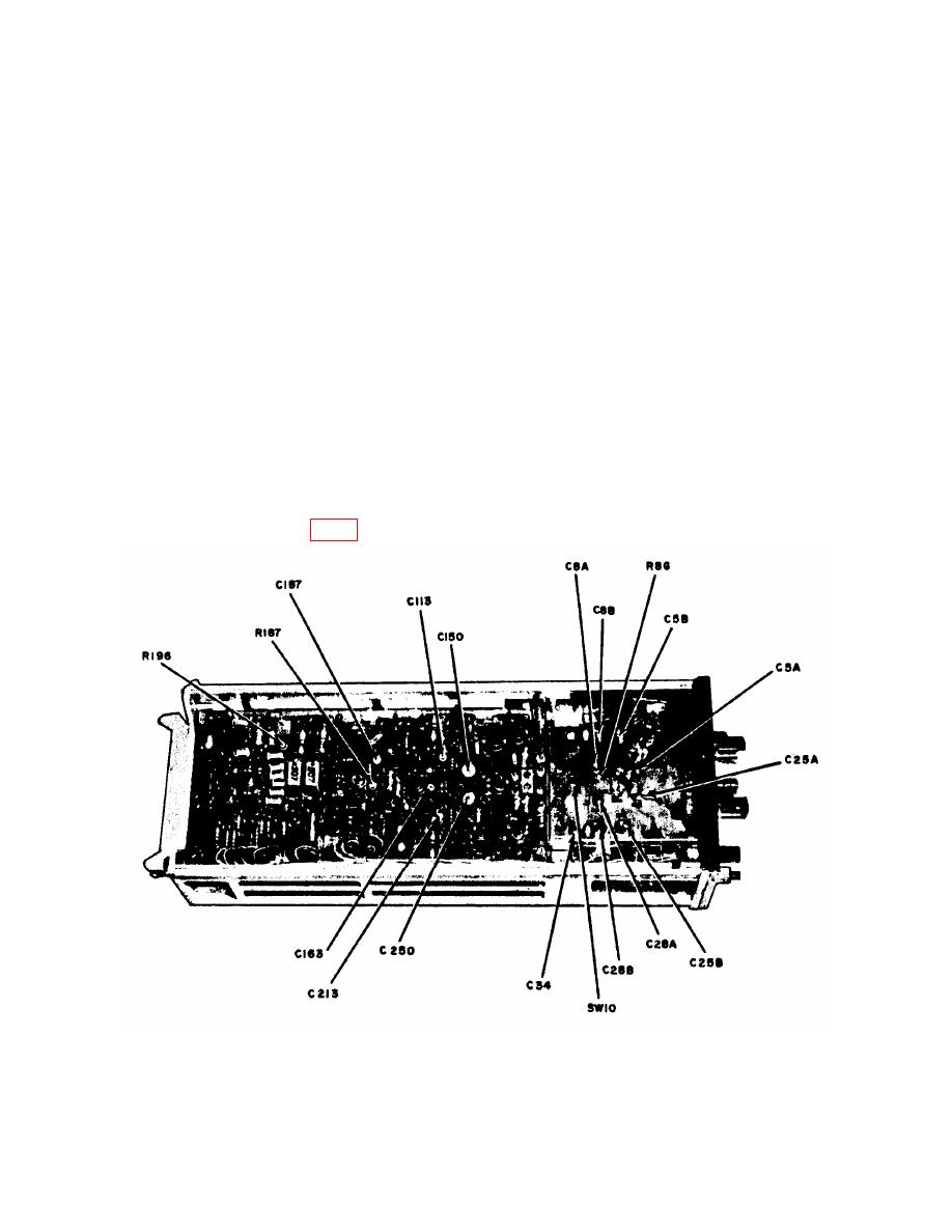
(11) SW 10 switch (fig. 1) fully ccw (R in = 1 MΩ).

