
TB 9-6625-2134-24
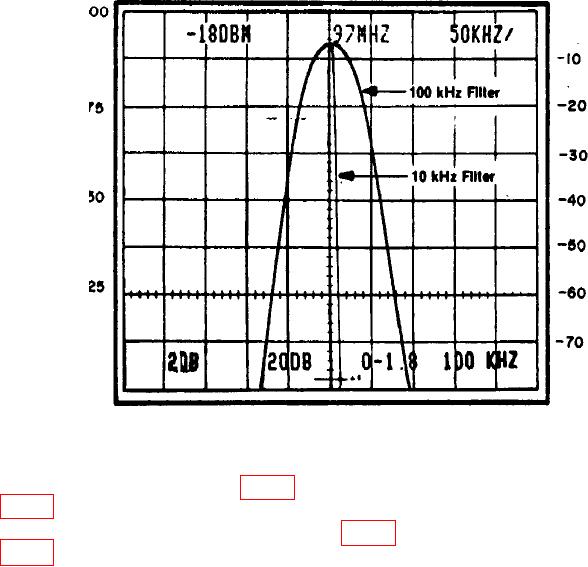
Figure 19. 100 kHz Filter Response.
(240) Push POWER switch to off.
(241) Disconnect P693 (fig. 17) (10 MHz signal) (VR #2 input) and, connect to J693
(fig. 20) (input VR #1).
(242) Connect P683 (output VR #1, fig. 17) to input of (log amplifier board) J621
(fig. 18) and pull POWER switch to on.
(243) Position controls as listed in (a) through (d) below:
(a) FREQUENCY control to 100 MHz.
(b) FREQUENCY SPAN/DIV to 500 kHz.
(c) RESOLUTION BANDWIDTH control to 100 kHz.
(d) REFERENCE LEVEL control to -20 dBm.
(244) Adjust FREQUENCY control to center signal on crt.
(245) Press VERTICAL DISPLAY 2 dB/DIV pushbutton to on and adjust
REFERENCE LEVEL control for a 7 division signal on crt.
(246) Adjust FREQUENCY SPAN/DIV control to 10 kHz and RESOLUTION
BANDWIDTH control to 10 kHz.
(247) Adjust FREQUENCY control until response is centered on crt display.
(248) Adjust FREQUNCY SPAN/DIV control to 50 kHz and RESOLUTION
BANDWIDTH control to 100 kHz.
34

