
TB 9-6625-2135-24
19. Dc Current
a. Performance Check
(1) Connect calibrator OUTPUT HI and LO to TI A and COM.
mA pushbutton.
(2) Press TI FUNCTION
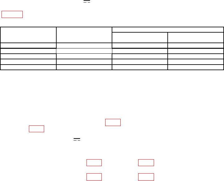
(3) Press TI RANGE pushbuttons and set calibrator output for settings listed in
table 10. TI will indicate within limits specified.
Table 10. Dc Current
Test instrument
Calibrator output
Test instrument indications
RANGE
pushbuttons
Min
Max
200 A
A
A
A
190
189.85
190.15
2
1.9
mA
1.8985
mA
1.9015
mA
20
19
mA
18.985
mA
19.015
mA
200
190
mA
189.7
mA
190.3
mA
2000
1.9
A
1890.3
mA
1909.7
mA
b. Adjustments. No adjustments can be made.
20. Power Supply
NOTE
Do not perform power supply check if all other parameters are
within tolerance.
a. Measure voltage at +7V TEST PAD (fig. 2) with multimeter. If required, adjust +7V
ADJ R717 (fig. 2) for a multimeter indication between 6.99 and 7.01 V dc (R).
V pushbuttons simultaneously.
b. Press TI FUNCTION
V and
c. Press TI RANGE 20 pushbutton.
and COM.
d. Short TI V
of 0 100 V (R).
of 0 200 V (R).
21. Final Procedure
a. Deenergize and disconnect all equipment.
b. Annotate and affix DA Label/Form in accordance with TB 750-25.
15/(16 Blank)

