
TB 9-6625-2138-24
(2) Adjust oscilloscope controls as required to view one complete cycle of waveform.
If waveform does not have a 50 percent duty cycle, perform b below.
(3) Set PATTERN switch to (20)-1 and CLOCK switch to 75.
(4) Momentarily set START/STOP switch to START. Observe JITTER readout for
one minute. JITTER readout indication will be 2 percent or less.
b. Adjustments. Adjust A14R16 (fig. 1) for an observed duty cycle of 50 percent (R).
9. INT XMIT Clock
a. Performance Check
(1) Connect frequency counter to INT XMIT CLOCK connector (rear panel).
(2) Set COUNT D/O COUNT C/L switch A1S1 (fig. 1) to COUNT D/O.
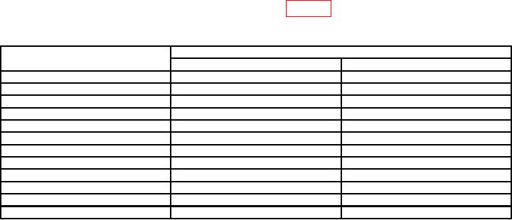
(3) Set CLOCK switch to settings listed in table 3. Frequency counter indications
will be within limits specified.
Table 3. INT XMIT Clock Accuracy
Test instrument
Frequency counter indications (Hz)
CLOCK switch settings
Min
Max
9600
9597.12
9602.88
7200
7128.00
7272.00
4800
4752.00
4848.00
3600
3564.00
3636.00
2400
2376.00
2424.00
1800
1782.00
1818.00
1200
1188.00
1212.00
600
594.00
606.00
300
297.00
303.00
200
198.00
202.00
150
148.50
151.50
75
74.25
75.75
(4) Set CLOCK switch to 9600.
t
(5) Connect oscilloscope to INT XMIT CLOCK (rear panel) connector using a 50
ermination. Waveform amplitude will be no less than 2 V peak.
(6) Set PATTERN switch to 1:1 and OFF/LOOP switch to OFF.
termination to BITS LOST connector (rear
(7) Connect oscilloscope without 50
panel). Waveform amplitude will be no less than 1.5 V peak.
(8) Connect frequency counter to BITS LOST connector.
(9) Set CLOCK switch to 75. Frequency counter indication will be between 70 and 80 Hz.
(10) Observe that OUT OF LOCK and LOSS OF DATA (RCV DATA INV on some
models) indicators are on.
(11) Set OFF/LOOP switch to LOOP. Frequency counter indication will be between
0 and 1 Hz.
b. Adjustments. No adjustments can be made.

