
TB 9-6625-2139-24
(c) B DELAY TIME POSITION control fully ccw.
(d) B TRIGGER LEVEL control fully cw.
(e) A TRIGGER NORM pushbutton pressed.
(2) Connect oscilloscope calibrator CHAN 1 to TI CH 1 using a 50 :
feedthrough termination.
(3) Press oscilloscope calibrator MARKER pushbutton to illuminate green LED
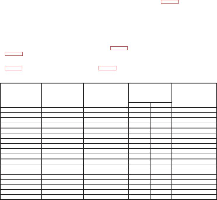
and set oscilloscope calibrator output for settings listed in first row in table 9.
(4) Adjust A TRIGGER LEVEL, A INTENSITY, and CH 1 POSITION controls
for suitable viewing.
(5) Adjust horizontal POSITION control to aline 2d time marker with 2d vertical
graticule line.
(6) Rotate oscilloscope calibrator knob located below EDIT FIELD pushbutton to
and TI linearity will be within limits listed in table 9; if not, perform adjustments listed in
(7) Repeat technique of steps (4) through (6) above for remaining rows listed in
Table 9. A Sweep Timing
Test instrument
Oscilloscope
Oscilloscope
linearity
Test instrument
calibrator
calibrator
Test instrument
0.1 division over any
A AND B SEC/DIV
Err display limits
MARKER
adjustments
2 center 8 divisions
switch settings
output settings
r%
Yes
No
b(l) thru (11)
50
nS/D
2
0.05 Ps
2
0.1 Ps
0.1
PS/D
2
0.2 Ps
0.2
PS/D
2
0.5 Ps
0.5
PS/D
2
1
Ps
1
PS/D
2
2
Ps
2
PS/D
2
5
Ps
5
PS/D
2
10
Ps
10
PS/D
20
S/D
2
20
Ps
50
S/D
2
50
Ps
0.1 ms
0.1
mS/D
2
0.2 ms
0.2
mS/D
2
0.5 ms
0.5
mS/D
2
1
ms
1
mS/D
2
2
ms
2
mS/D
2
5
ms
5
mS/D
2
10
ms
10
mS/D
2
20
ms
20
mS/D
2

