
TB 9-6625-2139-35
(36) Remove 50Ω feedthrough termination and connect oscilloscope calibrator CHAN
1 to TI CH 1.
(37) Position controls as listed in (a) and (b) below:
(a) HORIZONTAL MODE switch to A.
(b) A TRIGGER P-P AUTO pushbutton pressed.
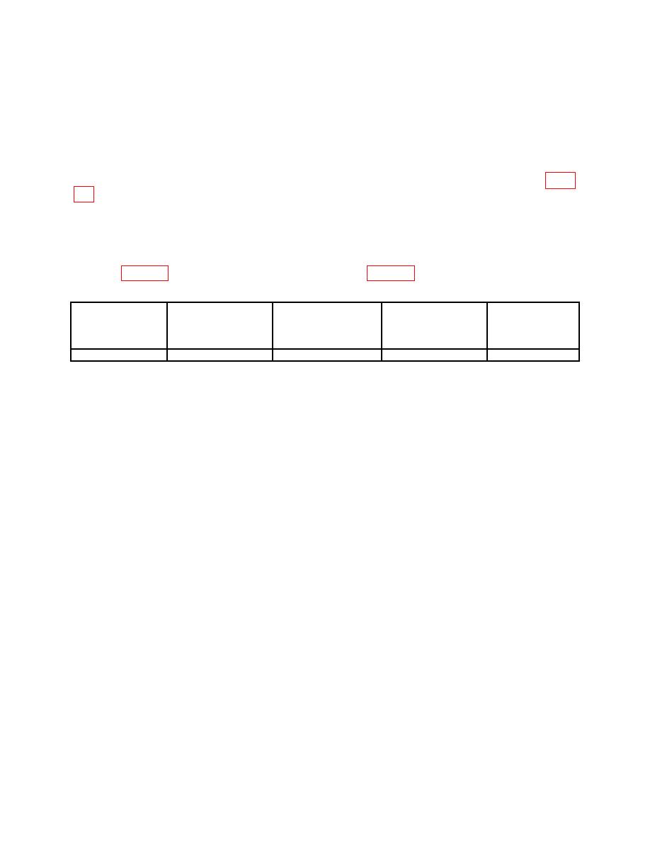
(38) Set TI switch settings and oscilloscope calibrator output setting as listed in table
(39) Adjust A INTENSITY, CH 2 POSITION (vertical adjustment) or POSITION
(horizontal adjustment) controls for suitable viewing.
(40) Rotate oscilloscope calibrator knob located below EDIT FIELD pushbutton to
for 5 divisions of horizontal display. Oscilloscope calibrator err display will be within limits
Table 16. Bandwidth
Oscilloscope
Test instrument
Test instrument
calibrator
Oscilloscope
A AND B SEC/DIV
CH 1 VOLTS/DIV
Err display limits
Test instrument
calibrator VOLTAGE
%
switch settings
adjustments
output settings
switch settings
10 m
X-Y
50 mV at 1 kHz
3
b(37) and (39)
b. Adjustments
(1) Position controls as listed in (a) through (c) below:
(a) HORIZONTAL MODE switch to A.
(b) A AND B SEC/DIV switches to .1 ms.
(c) X10 CAL control to in position.
(2) Set oscilloscope calibrator MARKER output to .1 mS/D.
(3) Adjust horizontal POSITION control to aline 1st time marker with the 1st
(extreme left) vertical graticule line.
(4) Adjust R740 (fig. 1) for 1 time marker per division over the center 8 divisions
(R).
(5) Set HORIZONTAL MODE switch to B and adjust B INTENSITY control for
suitable viewing. Adjust horizontal POSITION control to aline 1st time marker with 1st
vertical graticule line.
(6) Adjust R730 (fig. 1) for 1 time marker per division over the center 8 divisions
(R).
(7) Set HORIZONTAL MODE switch to A and pull X10 CAL control to out
position.
(8) Set oscilloscope calibrator MARKER output to 10 S/D.
(9) Adjust horizontal POSITION control to aline the nearest time marker to the lst
vertical graticule line.
22

