
TB 9-6625-2142-40
a. Remove side covers from TI and connect TI to sampling sweep unit as shown in
figure 1 and in accordance with special instructions in b and c below.
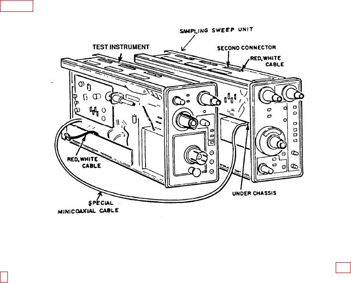
Figure 1. Special connection, AM-6787/U, Tektronix (Type 7S11).
b. Remove minicoaxial connector (second connector with red and white wire) from top
of sampling sweep unit and cover loose end with tape to avoid contact with components (fig.
1). Insert special minicoaxial cable through chassis of sampling sweep unit and connect to
second connector.
c. Remove coaxial cable connector from TI left side second connector (red and white
wire on TI inner channel control board) and cover loose end with tape. Connect other end of
special minicoaxial cable to second connector.
d. Install sampling sweep unit in oscilloscope No. 1 HORIZ compartment. Connect TI
to RIGHT VERT compartment, using extender.
e. Install sampling head in TI.
f. Position TI controls as listed in (1) through (7) below:
(1) DELAY control to midrange.
(2) +UP pushbutton pressed.
(3) DC OFFSET 1 V and FINE controls to midrange.
(4) mVOLTS/DIV switch to 200.
(5) VARIABLE (CAL IN) control pressed.
5

