
TB 9-6625-2142-40
(16) Connect oscilloscope calibrator to sampling head.
(17) Set oscilloscope calibrator for volt mode and a 10 kHz, 2 V pk-pk signal.
NOTE
Adjust TI DC OFFSET and FINE controls as necessary for
convenient vertical position of square wave on crt display when
performing (18) through (34) below.
(18) Adjust sampling sweep unit TRIG LEVEL and TIME POSITION controls for
stable square wave presentation with leading edge positioned on center vertical graticule
line. If waveform is not a well-defined square wave, perform b below.
(19) Adjust GAIN (front panel) control for 5 divisions of vertical deflection on crt
display.
(20) Press SMOOTH pushbutton.
(21) Adjust oscilloscope calibrator for 5 divisions of vertical deflection on crt display.
Oscilloscope calibrator readout will indicate within 6%.
(22) Press NORMAL pushbutton.
(23) Set oscilloscope calibrator for a 1 V pk-pk signal.
(24) Set TI mVOLTS/DIV switch to 100.
(25) Adjust oscilloscope calibrator 5 divisions of vertical deflection on crt display.
Oscilloscope calibrator will indicate within 3%.
(26) Press SMOOTH pushbutton.
(27) Adjust oscilloscope calibrator for 5 divisions of vertical deflection on crt display.
Oscilloscope calibrator will indicate within 6%.
(28) Repeat technique of (22) through (27) above for each mVOLTS/DIV switch
setting listed in table 4. If oscilloscope calibrator does not indicate within specified
tolerances, adjust TI GAIN (front panel) control to bring all ranges within tolerance.
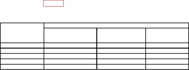
Table 4. Vertical Deflection Gain Accuracy
Test instrument
Oscilloscope calibrator
mVOLTS/Div
switch
Output
Normal
Smooth
settings
3%
6%
50
0.5
V
3%
6%
20
0.2
V
3%
6%
10
100
mV
3%
6%
5
50
mV
3%
6%
2
20
mV
(29) Press NORMAL pushbutton.
(30) Set TI mVOLTS/DIV switch to 200.
(31) Set oscilloscope calibrator for mode volt and 1.2 V pk-pk at 1 kHz.
(32) Adjust oscilloscope calibrator output for 3 division of vertical deflection on
crt display.
8

