
TB 9-6625-2144-35
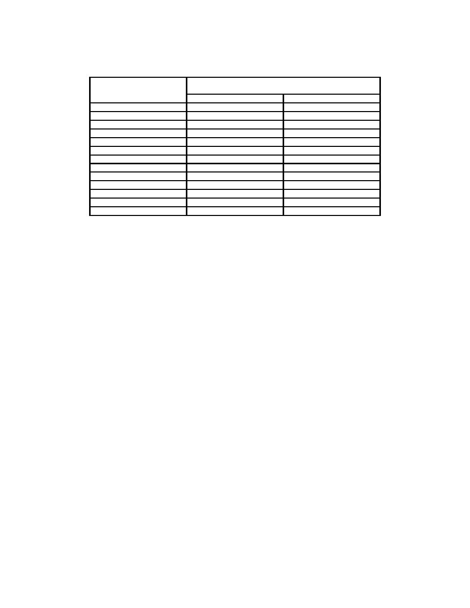
Table 5. Frequency Meter AN/UPM-29
Test instrument
Frequency counter
frequency
indications (GHz)
MC/10 dial settings
Min
Max
1580
15.792
15.808
1590
15.892
15.908
1600
15.992
16.008
1610
16.092
16.108
1620
16.192
16.208
1630
16.292
16.308
1640
16.392
16.408
1650
16.492
16.508
1660
16.592
16.608
1670
16.692
16.708
1680
16.792
16.808
1690
16.892
16.908
1700
16.992
17.008
b. Adjustments. No adjustments can be made.
9. Signal Generator Range
a. Performance Check
(1) Set TRAN/TEST/RECV switch to TEST (red dot) position and adjust PHASE
control for maximum peak indication of SET POWER meter. Adjust POWER SET control
as necessary to maintain on-scale indication.
NOTE
The PHASE control has several settings at which peak
deflection can be obtained on the power meter. Select the
setting that provides the most stable operation.
technique of (a) through (d) below:
(a) Slowly adjust FREQUENCY control until SET POWER meter indication
dips sharply. Note FREQUENCY MC/10 dial indication.
(b) Slightly increase or decrease toward 8.5 GHz (15.8 GHz) SIGNAL FREQ
control setting and readjust PHASE control to maintain peak indication of power meter.
(c) Continue process of (a) and (b) above until a sharp dip occurs when
FREQUENCY MC/10 dial indicates 850 (1580).
FREQUENCY MC/10 dial to a point at least 100 MHz away from TI signal generator
frequency and adjust POWER SET control for indication of SET POWER on SET
POWER meter.
7

