
TB 9-6625-2155-35
(6) Record the measuring receiver frequency indication as reference.
(7) Calculate the minimum and maximum limits for the 4 GHz rows in table 3 using
the formula below:
Minimum = (Reference + TI increment amount) FREQ INCR setting
Maximum = (Reference + TI increment amount) + FREQ INCR setting
(8) Press the TI FREQ INCREMENT up arrow key three times as indicated in
(9) Press the TI FREQ INCREMENT down arrow key four times as indicated in
table, and verify that the indication is within the tolerances calculated in (7) above.
(10) Repeat (4) (e) through (9) above for settings of FREQUENCY 8 GHz with
FREQ INCR of 2 kHz, and FREQUENCY 15 GHz with FREQ INCR of 3 kHz.
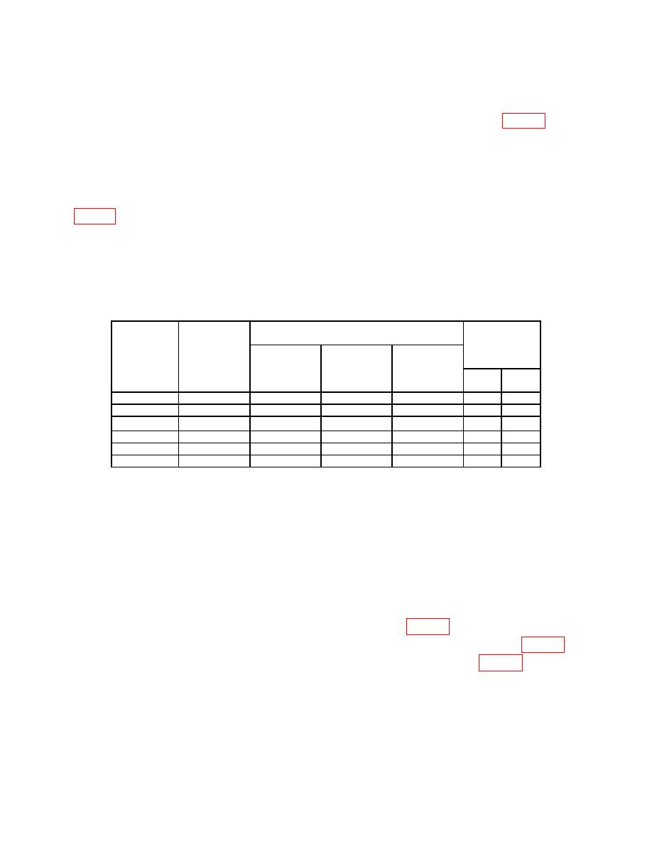
Test instrument
Measuring
Step
receiver
Local
Tolerance
Increment
increment
Frequency
offset
amount
direction
(GHz)
(MHz)
(GHz)
Min
Max
4.12053
4120.530
4.000000
UPUPUP
.003
4.12053
4120.530
4.000000
DNDNDNDN
-.001
8.12053
8120.530
8.000000
UPUPUP
.006
8.12053
8120.530
8.000000
DNDNDNDN
-.002
15.12053
15120.530
15
UPUPUP
.009
15.12053
15120.530
15
DNDNDNDN
-.003
(11) Press TI keys as listed in (a) through (f) below.
(a)
RCL 0.
(b)
Adjust OUTPUT LEVEL for 0 dB.
(c)
ALC INTERNAL on.
(d)
RF OUTPUT on.
(e)
FREQ INCR, 1, 1, 1, ., 1, 1, 3, and MHz.
(f)
FREQUENCY, 2, GHz.
(12) Set local oscillator and measuring receiver to measure 2 GHz, using the local
oscillator, and measuring receiver offset frequencies listed in table 4.
(13) Verify that the measuring receiver indicates within tolerances listed in table 4.
(14) Repeat (11) (e) through (13) above for remaining settings in table 4 verifying
measuring receiver indicates within the tolerances listed.
7

