
TB 9-6625-2155-35
(2) Press TI keys as listed in (a) through (e) below.
(a)
RCL 0.
(b)
Adjust OUTPUT LEVEL for -13 dB.
(c)
ALC INTERNAL on.
(d)
RF OUTPUT on.
(e)
FREQUENCY, 16.6, GHz.
(3) Set audio analyzer as listed in (a) through (d) below.
(a)
PRGM 99 ENTER RCL.
600Ω output.
(b)
(c)
Source frequency 1 kHz.
(d)
Source level 0.7 V.
(4) Set measuring receiver to measure amplitude modulation, with +PEAK detector,
high pass and Lo pass filters off and at a frequency of 16.6 GHz.
(5) Press TI AM MTR and 100%AM keys. Adjust the audio analyzer output level of
a 50.0 0.1% AM indication on the measuring receiver.
(6) If the TI meter does not indicate within limits listed in table 15 perform b below.
(7) Repeat (5) and (6) above for the 75% AM meter indication listed in table 15.
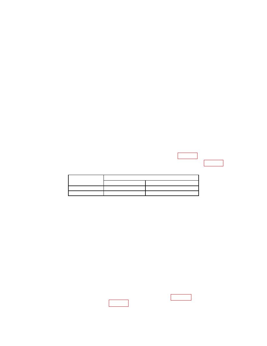
Table 15. AM Meter
Test instrument meter indication
Test
description
Min
Max
50% AM meter
43.5
56.5
75% AM meter
70
80
(8) Press TI keys as listed in (a) through (b) below.
(a) Adjust OUTPUT LEVEL for -0 dB.
(b) FREQUENCY, 3.9, GHz.
(9) Set audio analyzer as listed in (a) through (b) below.
(a) Source frequency 1 kHz.
(b) Source level 0.425 V.
(10) Set measuring receiver to measure amplitude modulation, with +PEAK detector,
high pass and Lo pass filters off and at a frequency of 3.9 GHz.
(11) Press TI AM MTR and 100%AM keys. Adjust the audio analyzer output level of
a 30.0 0.05% AM indication on the measuring receiver.
(12) Set audio analyzer to measure LEVEL and set units to dB then select
RATIO mode.
(13) Set the audio analyzer to the frequencies listed in table 16; the audio analyzer
will indicate within limits listed in table 16.
23

