
TB 9-6625-2162-24
(13) Record frequency counter indication.
Subtract this indication from the
indication recorded in (11) above. If the result is not between 0.275 and 0.283 MHz, adjust
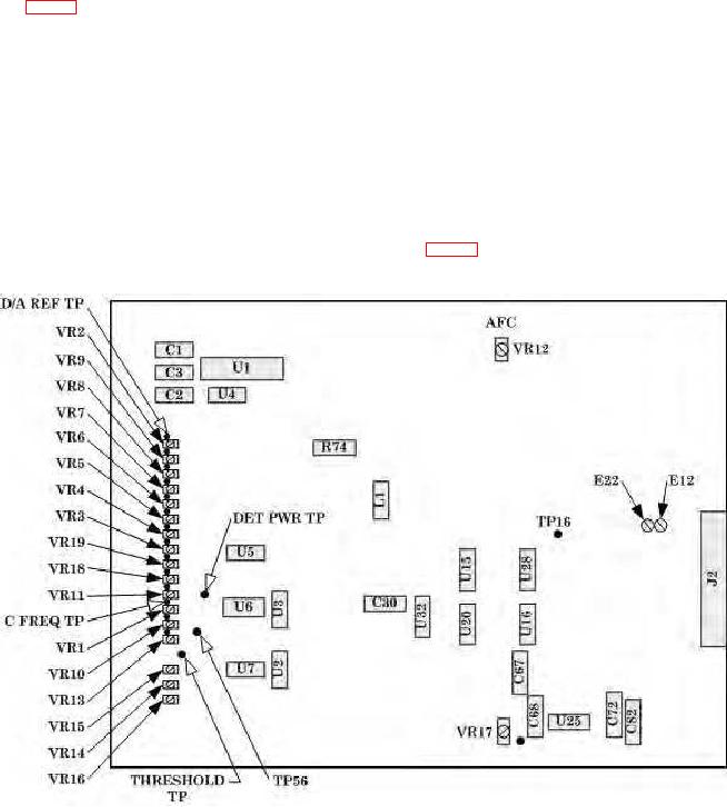
VR12 (fig. 1) as listed in (a) and (b) below.
(a) For a result greater than 0.283 MHz turn VR12 slightly ccw (R).
(b) For a result less than 0.275 MHz turn VR12 slightly cw (R).
(14) Press E on keyboard until display indicates 3 and repeat (11) through (13) above
until no further adjustments are necessary.
RF IN/OUT.
(16) Repeat 8 a (1) through (3) above.
(17) Set ATTENUATION DB 0-80 switch to 10.
(18) Connect multimeter to C FREQ test point (fig. 1) and chassis ground.
Figure 1. Microwave interface 1A1A3 board - component location.
7

