
TB 9-6625-2162-24
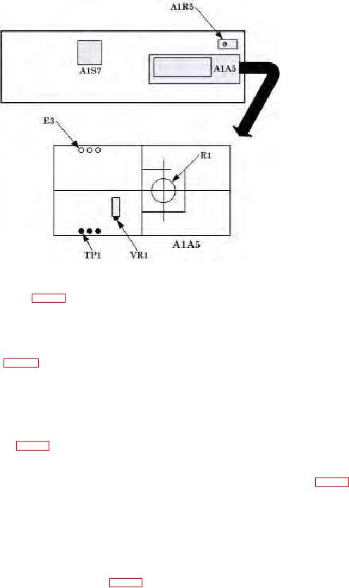
Figure 2. RF Gunn oscillator A1A5 component location.
(19) Connect TP56 (fig. 1) to chassis ground.
(20) Adjust FREQ 8.4 TO 10.0 GHz COARSE control for an 8400 5 MHz frequency
counter indication.
(21) If multimeter does not indicate between +1.1 and +1.3 V dc loosen the 3 clamp
screws that hold R1 (fig. 2) in position. Rotate R1 until multimeter indicates +1.2 V dc (R).
(22) Tighten the 3 clamp screws and ensure multimeter indicates between +1.1
and +1.3 V dc.
(23) Adjust FREQ 8.4 TO 10.0 GHz COARSE control for a 10,000 5 MHz
frequency counter indication.
(24) Adjust VR1 (fig. 1) for a multimeter indication of 9.5 0.1 V dc (R).
(25) Repeat (20) through (24) above until no further adjustment can be made.
(26) Disconnect multimeter from TI and remove ground lead from TP56 (fig. 1).
NOTE
For microwave interface board 1A1A3 (P/N 58139-40010),
perform (27) through (32) below. For microwave interface
board 1A1A3 (P/N 5813940010-1), perform (33) through (35)
below.
(27) Connect oscilloscope to TP16 (fig. 1) and ground.
(28) While observing oscilloscope, slowly turn FREQ 8.4 TO 10.0 GHz COARSE
control from 8400 to 10000 MHz and record the lowest peak to peak voltage indication.
8

