
TB 9-6625-2162-24
minimum and maximum display indications.
If indications noted are not 0.0 1
dBm, perform b (1) through (6) below.
(7) Set ATTENUATION DB FINE control to mid-range. Adjust FREQ 8.4 TO
10.0 GHz COARSE control from fully ccw to fully cw and note maximum power meter
indication.
(8) Readjust FREQ 8.4 TO 10.0 GHz COARSE control to obtain power meter
indication noted in (7) above. Set ATTENUATION DB FINE control fully ccw. If TI
display does not go blank, perform b (7) below.
(9) Adjust FREQ 8.4 TO 10.0 GHz COARSE and FINE controls for a display
indication of 8400 20 MHz.
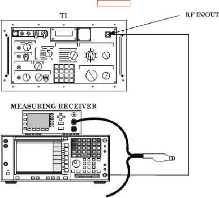
(10) Connect equipment as shown in figure 3 below.
Figure 3. CW Output power.
(11) Configure measuring receiver to spectrum analyzer mode.
NOTE
Steps (12) through (15) below must be performed and the
measuring receiver (spectrum analyzer) indications (at 8400,
9200, and 10000 MHz) recorded for each out-of tolerance
ATTENUATION DB 0-80 switch position prior to performing
adjustments in b (8) through (12) below.
(12) Set DISPLAY SELECT switch to RF SIG PWR (DBM) and ATTENUATION
DB 0-80 switch to 0. Adjust ATTENUATION DB FINE control for a TI display indication
of 0.0 dBm.
10

