
TB 9-6625-2162-24
NOTE
All references to measuring receiver indications in (8) through
(14) below and b (1) through (26) must be computed from the
output coupling ratio recorded in (5) above for the applicable
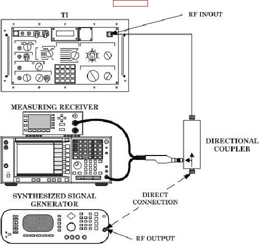
(7) Connect equipment as shown in figure 5.
Figure 5. Power measurement.
(8) Position controls as listed in (a) through (d) below:
MODE switch to RADAR CW.
(a)
DISPLAY SELECT switch to RF IN PWR (DBM).
(b)
TRIGGER switch to RF.
(c)
ATTENUATION DB 0-80 switch to 0.
(d)
(9) Set synthesized signal generator for an 8.4 GHz output. Adjust output level
until measuring receiver indicates a directional coupler output of +8.0 dBm. If TI display
does not indicate 8.0 1 dBm, perform b (1) through (22) below.
(10) Repeat (9) above for each 0.1 GHz increment between 8.4 and 10.0 GHz.
15

