
TB 9-6625-2162-24
for internal gating.
(15) Set DISPLAY SELECT switch to RANGE RATE (KNS) and press 0 then E on
keyboard.
(16) Set DISPLAY SELECT switch to RANGE (YDS) and press 250 then E on
table 9, perform b below.
(17) Repeat technique of (16) above for keyboard entries listed in table 9. Frequency
counter will indicate within limits specified in table 9.
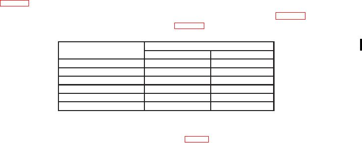
Table 9. Range
Test instrument
Frequency counter indications (μs)
keyboard entries
Min
Max
250 and then E
1.464
1.568
1000 and then E
6.039
6.161
2000 and then E
12.139
12.261
10,000 and then E
60.695
61.305
20,000 and then E
121.390
122.610
40,000 and then E
242.780
245.220
b. Adjustments. Set DISPLAY SELECT switch to RANGE RATE (KNS). Press
100, +/-, and then E on keyboard. Adjust VR11 (fig. 1) until frequency counter, equates as
close as possible to 1.525 Ps (R).
NOTE
VR11 adjusts in steps of 0.061 Ps.
13. Pulse Output Power
a. Performance Check
(1) Connect TRIG OUT to oscilloscope channel 2 input, and connect RF IN/OUT to
oscilloscope channel 1 input, using semiconductor device.
(2) Set oscilloscope for channel 2 triggering with a 1 ms time base and channel 1 dc
coupled, 10 mV/div, and 1 MŸ input.
(3) Position controls as listed in (a) through (e) below:
MODE switch to SIG GEN PULSE.
(a)
DISPLAY SELECT switch to FREQ (MHz).
(b)
ATTENUATION DB 0-80 switch to 0.
(c)
TRIGGER switch to INT.
(d)
TRIG OUT switch to POS.
(e)
(4) Adjust FREQ 8.4 to 10.0 GHz COARSE and FINE controls for a display
indication of 9200 5 MHz.
(5) Set DISPLAY SELECT switch to PRF (Hz) and adjust PRF control for a
display indication of 1000 r9 Hz.
Change 1

