
TB 9-6625-2163-24
b. Adjustments
(1) Install variable attenuator between RTS Main RF I/O connector and circulator
PORT 1. Set Menu 11 RF power to 0 dBm and adjust variable attenuator for -9 dBm on
peak power meter.
(2) On Menu 11 set CW to OFF.
(3) Disconnect cable from peak power meter and reconnect to TI Probe connector.
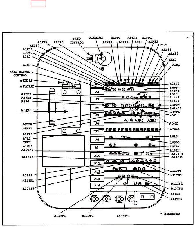
Adjust A8R5 (fig. 2) until ACCEPT light glows. Decrease RTS RF power by 1 dBm. TI
REJECT indicator will glow.
(4) Remove variable attenuator and reconnect circulator to MAIN RF I/O.
(5) Repeat a (1) through (5).
Figure 2. Test instrument adjustments and test points.
7

