
TB 9-6625-2164-35
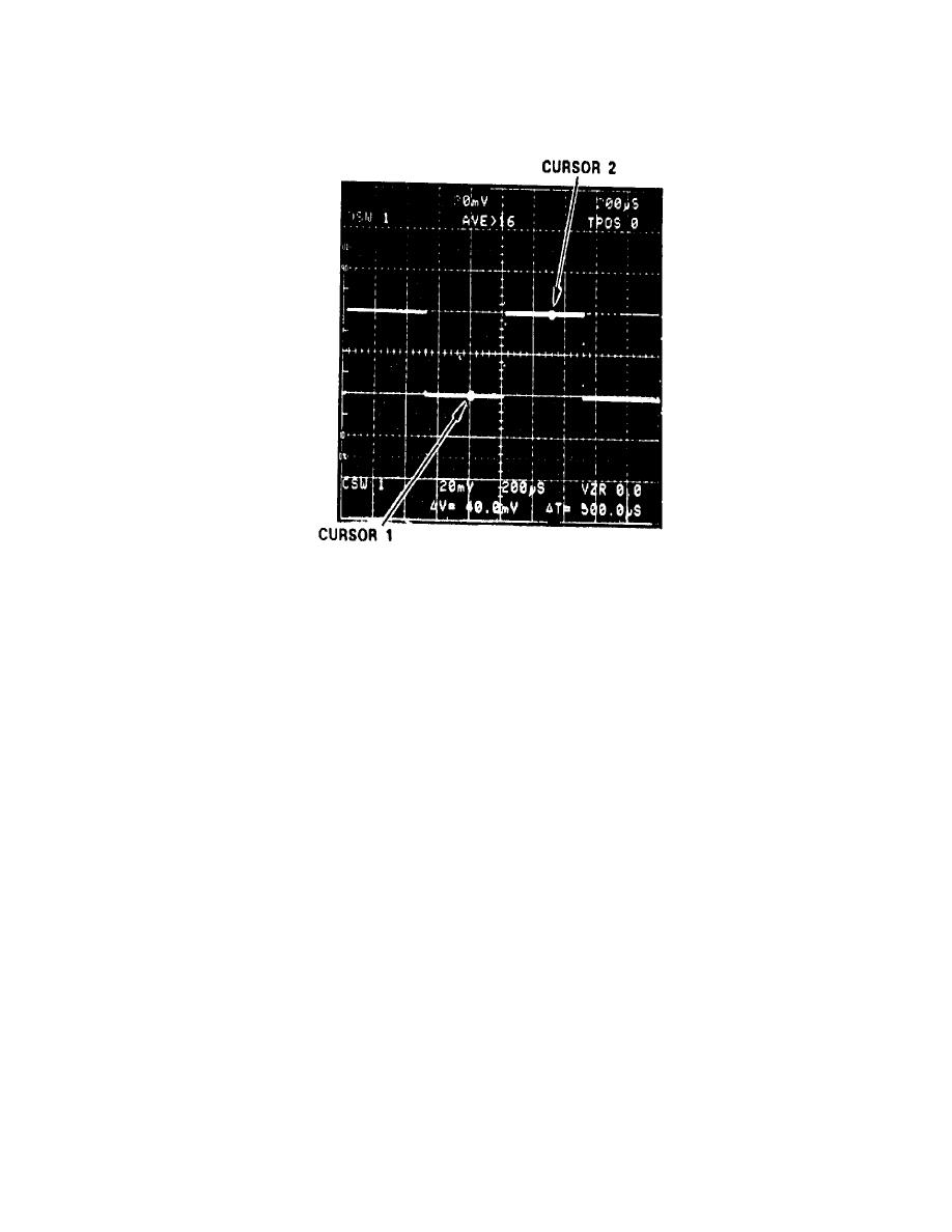
(8) Adjust CH 1 POSITION control to move 2 division display over the entire
graticule area. The CURSOR readout display should not vary more than 2.4 mV.
(9) Press AQR MODE CH 2→2 pushbutton.
(10) Connect oscilloscope calibrator SOURCE/MEASURE CHAN 1 output to TI CH 2
input and set CH 2 VOLTS/DIV to 20 mV.
(11) Adjust CH 2 POSITION control to move 2 division display over the entire
graticule area. The CURSOR readout display indication should not vary more than 2.4 mV.
(12) Press CH 1 and CH 2 GND pushbuttons.
(13) Adjust CH 2 POSITION control fully cw and then fully ccw. TI VZR display
indication will be at least 5.0 (cw) and -5.0 (ccw); if not, perform b (11) through (20) below.
(14) Press AQR MODE CH 1→1 pushbutton.
(15) Adjust CH 1 POSITION control fully cw then fully ccw. TI VZR display
indication will be at least 5.0 (cw) and -5.0 (ccw); if not, perform b (1) through (10) below.
14

