
TB 9-6625-2164-35
b. Adjustments
(1) Press MENU/TEST and MEMORY DISPLAY 4, 5, 6 and MENU/TEST pushbuttons.
(2) Position controls as listed in (a) through (d) below:
(a) Set CH 1 VOLTS/DIV switch to 10 mv.
(b) Press CH 1 GND pushbutton.
(c) Set TIME/DIV switch to 500 s.
(d) Adjust CH 1 POSITION control to aline trace with the center graticule line.
(3) Connect a shorting cable between TP1220 and TP520 TP GND (fig. 4). TI VZR
display readout will indicate between -0.2 and +0.2; if not, adjust CH 1 CENTERING R410
(4) Remove shorting cable from TP1220 and TP520 TP GND (fig. 4).
(5) Press CH 1 AC pushbutton and set VOLTS/DIV to 20 mV.
(6) Connect oscilloscope calibrator SOURCE/MEASURE CHAN 1 output to CH 1
input and adjust oscilloscope calibrator frequency for 1 kHz and amplitude for 50 mV.
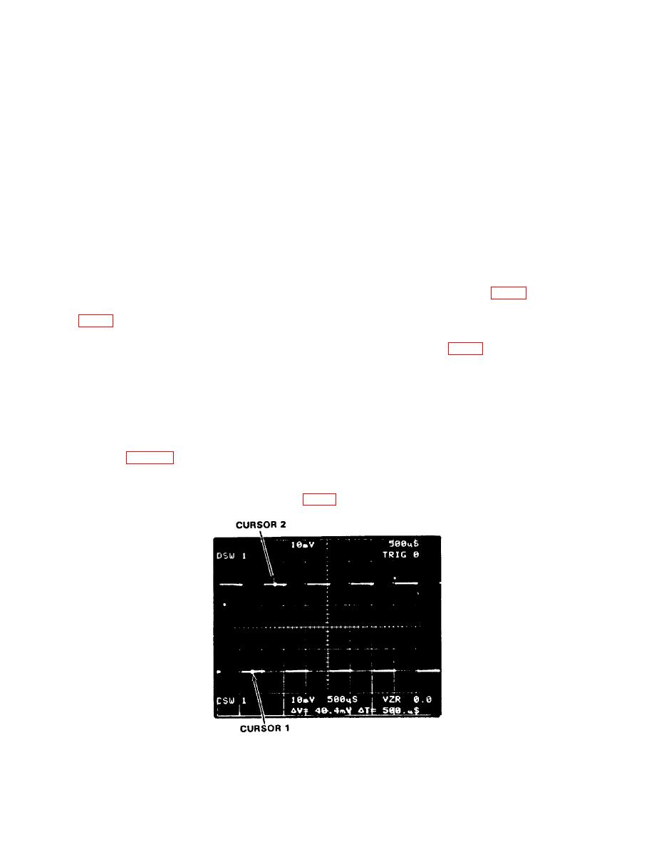
(7) Press f (function) and CURSORS ∆ ON pushbutton and adjust CURSORS as
shown in figure 8.
(8) Press AVE N pushbutton. CURSORS readout will indicate between 49.6 and
50.4 mW; if not, adjust CH 1 GAIN R344 (fig. 2) for ∆V=50.0 mV (R).
15

