
TB 9-6625-2171-35
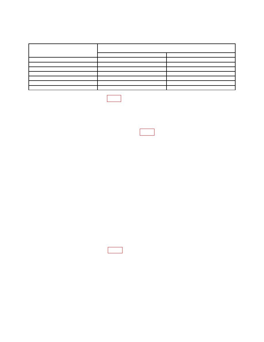
Table 5. VOR Bearing
Test instrument
VOR bearing
Zifor indications
switch positions
Min
Max
045
044.0
046.0
090
089.0
091.0
135
134.0
136.0
180
179.0
181.0
225
224.0
226.0
270
269.0
271.0
315
314.0
316.0
19. LOC DDM
a. Performance Check
(1)
Set VOR PWR switch to OFF and LOC PWR switch to ON. If VAR light is
illuminated, press light to extinguish.
(2)
Connect digital multimeter to A6J2 (fig. 3).
(3)
Press and hold LOC 150 Hz pushbutton. Record digital multimeter
indication.
(4)
Set LEFT-OC-RIGHT switch to LEFT. Record digital multimeter
indication.
(5)
Set LEFT-OC-RIGHT switch to RIGHT. Record digital multimeter
indication.
(6)
Release LOC 150 Hz pushbutton and press and hold LOC 90 Hz
pushbutton. Record digital multimeter indication.
(7)
Set LEFT-OC-RIGHT switch to OC. Record digital multimeter indication.
(8)
Set LEFT-OC-RIGHT switch to LEFT. Record digital multimeter
indication.
(9)
Release LOC 90 Hz pushbutton.
(10)
Subtract value recorded in (7) above from value recorded in (3) above. If
difference is not less than 1 mV, perform b below.
(11)
Divide value recorded in (8) above by value recorded in (4) above. Ratio will
be between 2.02 and 2.55.
(12)
Divide value recorded in (5) above by value recorded in (6) above. Ratio will
be between 2.02 and 2.55.
computed in a(10) above is less than 1 mV (R).
20. LOC Modulation
a. Performance Check
(1)
Connect measuring receiver power sensor module to TI J3. Position
measuring receiver controls to measure AM. Set LEFT-OC-RIGHT switch to OC.

