
TB 9-6625-2173-24
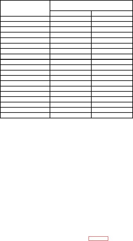
Table 7. Sweep Timing
Test instrument
SECONDS/DIV
Oscilloscope calibrator
switch settings
Marker
err r
50
ns
50
ns
3
3
0.1
Ps
0.1
Ps
2
0.2
Ps
0.2
Ps
2
0.5
Ps
0.5
Ps
2
2
Ps
2
Ps
2
5
Ps
5
Ps
2
10
Ps
10
Ps
2
20
Ps
20
Ps
2
50
Ps
50
Ps
0.1
ms
0.1
ms
2
0.5
ms
0.5
ms
2
1
ms
1
ms
2
2
ms
2
ms
2
5
ms
5
ms
2
10
ms
10
ms
2
20
ms
20
ms
2
50
ms
50
ms
3
0.1
s
0.1
s
3
0.2
s
0.2
s
3
(11) Connect oscilloscope calibrator EXT TRIG/CHAN 5 to TI EXT TRIG input
using 50 : feedthrough termination.
(12) Set PULL X10 HORIZ MAG switch to out position.
(13) Set TI TRIGGERING SOURCE switch to EXT.
(14) Activate oscilloscope calibrator CHAN 5 for external trigger operation at
this time.
(15) Press TI TRIGGERING MODE pushbutton to NORM.
(16) Set TI SECOND/DIV switch to .2 ms and oscilloscope calibrator MARKER
output for 20 Ps.
(17) Excluding the first 50 ns and all after the first 100 divisions of magnified sweep,
adjust TRIGGERING LEVEL and horizontal POSITION controls to align 2d time marker
with 2d vertical graticule line.
(18) Rotate oscilloscope calibrator EDIT FIELD knob to align one time marker per
division between 2d and 10th vertical graticule lines. If oscilloscope calibrator err display
readout does not indicate within r3%, perform b (5) through (15) below.
(19) Repeat technique of (11) through (18) above for oscilloscope calibrator MARKER
outputs and SECONDS/DIV switch settings listed in table 8. Oscilloscope calibrator err
display readout will be within limits as listed in table (8).
26

