
TB 9-6625-2173-35
(3) Adjust horizontal POSITION control and rotate oscilloscope calibrator EDIT
calibrator err display readout does not indicate within 3%, perform b (1) below:
(4) Push SECONDS/DIV CAL control in and set SECONDS/DIV switch to 1 s.
(5) Set oscilloscope calibrator MARKER output to 1 s.
(6) Adjust horizontal POSITION control and rotate oscilloscope calibrator EDIT
calibrator err display readout does not indicate within 2%, perform b(2) below.
(7) Set SECONDS/DIV switch to .2 s.
(8) Set oscilloscope calibrator MARKER output to 0.2 s.
(9) Adjust horizontal POSITION control and rotate oscilloscope calibrator EDIT
calibrator err display readout does not indicate within 3%, perform b (2) below.
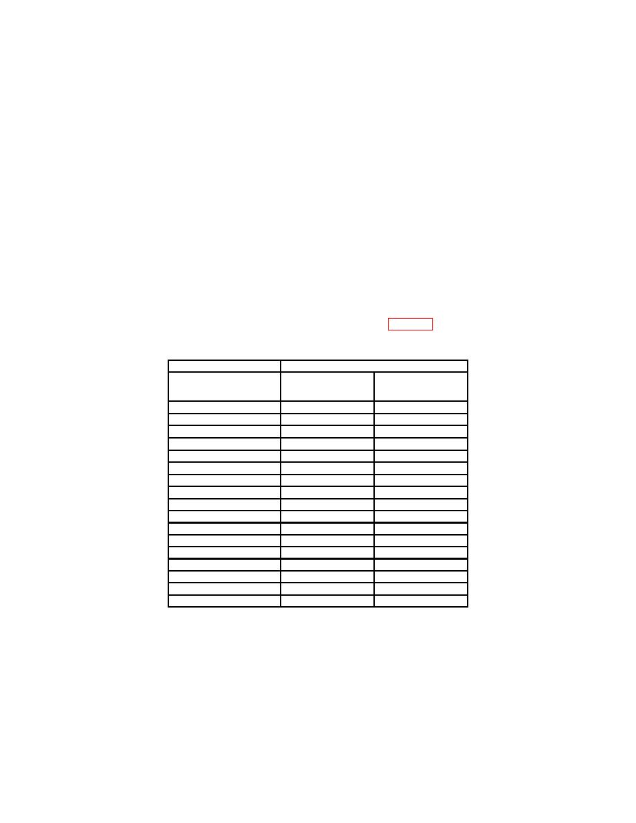
(10) Repeat technique of (7) through (9) above for oscilloscope calibrator and TI
err display will indicate within percent of error specified.
Test instrument
Oscilloscope calibrator
SECONDS/DIV
MARKER
err
()
switch settings
output
s
3
.5
.5
s
2
2
2
s
2
5
5
s
2
10
10
s
2
20
20
s
2
50
50
.1
m
.1
ms
2
.5
m
.5
ms
2
1
m
1
ms
2
2
m
2
ms
2
5
m
5
ms
2
10
m1
10
ms
2
20
m
20
ms
2
50
m
50
ms
2
.1
s
.1
s
3
.2
s
.2
s
3
.5
s
.5
s
3
1Press
and release COUPL AUTO pushbutton to normal.
b. Adjustments
NOTE
Interaction exists between adjustments in (1) and (2) below.
Repeat as necessary for best compromise.
14

