
TB 9-6625-2179-24
11. Input Power and Sensitivity
a. Performance Check
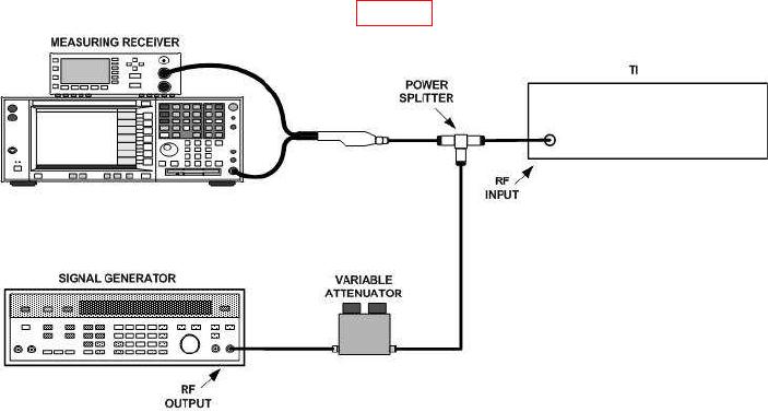
(1) Connect equipment as shown in figure 3.
Figure 3. Input power and sensitivity - - equipment setup.
(2) Connect sensor module to the power reference output. Perform sensor zero
and calibration.
(3) Configure measuring receiver to measure power.
(4) Set variable attenuator to 0 dB.
(5) Set signal generator controls for a 490 MHz cw output. Adjust output level
controls for a +10 dBm indication on measuring receiver.
(6) Press TI POWER key. TI MODULATION display will indicate between 9 and 11 dBm.
(7) Press TI POWER key to turn power measurement off.
(8) Adjust signal generator output level controls for a 0 dBm measuring receiver
indication.
NOTE
All variable attenuator indications in (9) through (20) below
must be computed from the test report for the variable
attenuator.
(9) Increase variable attenuator until TI FREQUENCY display indicates all dashes
(- - -) or an error code (i.e., 54).
(10) Variable attenuator will indicate 25 dB or greater.
(11) Repeat (4) above.

