
TB 9-6625-2184-35
(10) Repeat technique of (7) and (9) above for remaining frequencies listed in table 4.
Frequency counter and true rms voltmeter will indicate within limits specified. If
frequency counter does not indicate as specified, perform b (6) through (14) below.
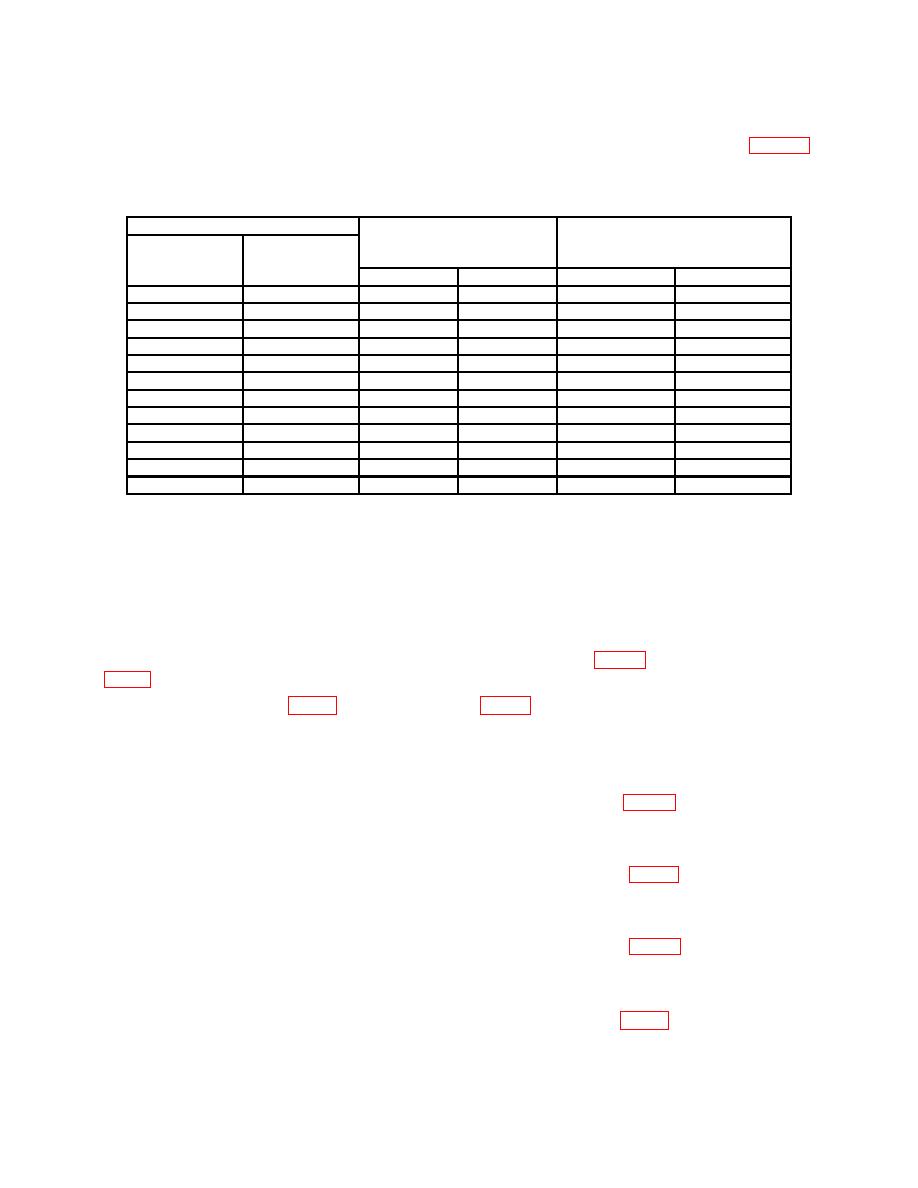
Test instrument
Ac voltmeter
Frequency counter
RANGE
Frequency
indications (dB)
indications (Hz)
switch
dial
positions
settings
Min
Max
Min
Max
X10
50
-1
+1
490
510
X10
70
-1
+1
686
714
X10
90
-1
+1
882
918
X10
120
-1
+1
1176
1224
X10
200
-1
+1
1960
2040
X10
300
-1
+1
2940
3060
X10
400
-1
+1
3920
4080
X10
500
-1
+1
4900
5100
X100
50
-1
+1
4900
5100
X100
500
-1
+1
49,000
51,000
X1000
50
-1
+1
49,000
51,000
X1000
500
-1
+1
490,000
510,000
(11) Vary autotransformer output between 105 and 125 V ac. Frequency counter will
remain between 490,000 and 510,000 Hz.
b. Adjustments
NOTE
Adjustments in parenthesis pertain to SG-71C/FCC.
(1) Connect multimeter between C7 and R23 junction (fig. 4), (for SG-71C/FCC,
fig. 2) and ground.
(2) Adjust R13 (fig. 1) (for SG71C/FCC, fig. 2), until true rms voltmeter indicates
22.5 V ac (R).
(3) Repeat a (1) through (5) above.
(4) Set frequency dial to 500 and RANGE switch to X1.
(5) Adjust X1 front panel control (for SG-71C/FCC, R9, fig. 2) until frequency
counter indicates 500 Hz (R).
(6) Set RANGE switch to X10.
(7) Adjust X10 front panel control (for SG-71C/FCC, R10, fig. 2) until frequency
counter indicates 5000 Hz (R).
(8) Set frequency dial to 50 and RANGE switch to X100.
counter indicates 5000 Hz (R).
(10) Set RANGE switch to X1000.
counter indicates 50,000 Hz (R).
7

