
TB 9-6625-2185-24
9. Basic Instrument Accuracy
a. Performance Check
(1) Press pushbuttons as listed in (a) through (h) below:
1, SELECT CHNL.
(a)
1, SELECT SENS.
(b)
MODE PWR, RANGE AUTO.
(c)
99, dB LIMITS HI.
(d)
99, CHS, dB LIMITS LO.
(e)
0, CAL FACTOR dB.
(f)
0, REF LEVEL dB.
(g)
ZERO (display will indicate cccc while zeroing, cc03 when complete).
(h)
(2) Connect TI sensor to PWR REF and press CAL pushbutton. If display does not
indicate from 0.998 to 1.002 mW, perform paragraph 10 below.
(3) Press MODE dB pushbutton.
(4) Position synthesizer/level generator controls for 50 MHz, 0 dBm output, and
connect power meter sensor to 50 : OUTPUT.
(5) Set synthesizer/level generator output for exactly 1 mW, using precision power
measurement technique in paragraph 8 a (7) through (12) above. Record error from 0.00
dBm indicated on synthesizer/level generator display as generator correction factor.
NOTE
The correction factor recorded in (5) above must be added to all
synthesizer/level generator output settings used in this
paragraph.
(6) Disconnect TI sensor from PWR REF and connect to synthesizer/level
generator 50 : OUTPUT.
(7) Position synthesizer/level generator controls for 50 MHz and output of +10 dBm.
If TI display does not indicate between +9.85 and +10.15, perform b (1) through (31) below.
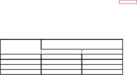
(8) Repeat technique of (7) above, using control settings listed in table 3. If TI
display does not indicate within limits specified, perform b (1) through (31) below.
NOTE
Actual value of 20 dB attenuator (p/o TI) must be known to
within 0.04 dB.
Table 3. Basic Instrument Accuracy
Synthesizer/level
Display indications (dBm)
generator
output (dBm)
Min
Max
+9.0
+08.85
+09.15
+8.0
+07.85
+08.15
+7.0
+06.85
+07.15
+6.0
+05.86
+06.14

