
TB 9-6625-2185-35
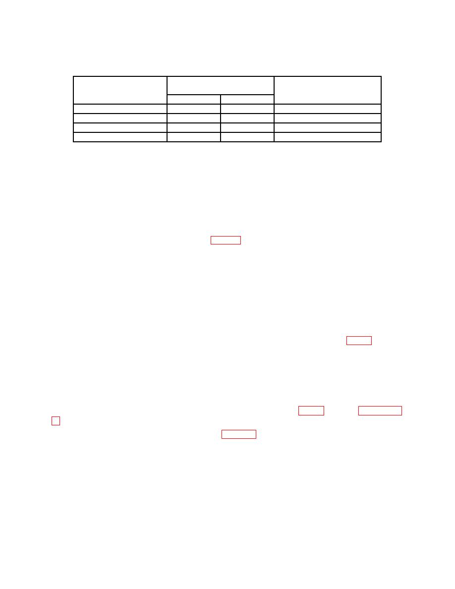
Level generator
Display
Record out-of-tolerance
output
indications
indications and
(dBm)
Min
Max
corresponding range
-24
-23.92
-24.08
Range 1
-14
-13.92
-14.08
Range 2
-4
-3.95
-4.05
Range 3
+6
+5.92
+6.08
Range 4
(28) Calculate upscale corrections for out-of-tolerance ranges using formula as
shown in example below:
Example:
New gain factor = old gain factor + (TI error X 1200)
NOTE
For every .01 dB of error, a correction of 12 counts must be
added or subtracted to gain factor. Gain factors were
recorded in (12) above and table 4.
Example:
Display indicates -24.16 dBm
Actual power level is -24.00 dBm
TI error is .16 dB low (add to gain factor)
Gain factor from table is 5032.
New gain factor = 5032 + (.16 X 1200)
New gain factor = 5224
(29) Set control board bit switch to CALIBRATE MODE 2 (AC CAL) (fig. 3).
(30) Press pushbuttons N, RANGE HOLD, XXXX, REF LVL dB.
NOTE
N is out-of-tolerance range, XXXX is new gain factor from
(28) above.
9a above.
(32) Connect equipment as shown in figure 2, CONNECTION A.
output to within RF power amplifier input operating range. Slowly increase RF power
amplifier gain control for a power meter indication of 0 dBm.
(34) Use precision power measurement technique, calculate and record calculated
power as P2.
17

