
TB 9-6625-2188-24
(8) Adjust FREQ VERN control to center position.
b. Adjustments
(1) Remove left side cover.
(2) Loosen set screws on shaft behind front panel of FREQUENCY Hz dial.
Tighten set screws (R).
9. Output Attenuator and Flatness
a. Performance Check
(1) Connect notch filter INPUT to TI OUTPUT.
(2) Connect multimeter to OUTPUT of notch filter.
(3) Position controls on notch filter as listed in (a) through (d) below:
NOTCH FREQUENCY switch to 1 kHz.
(a)
ADJUST FOR NULL controls to center.
(b)
MODE pushbutton to FLAT (out).
(c)
ATTEN pushbutton to 0 dB (out).
(d)
(4) If multimeter does not indicate between 0.756965 and 0.792639 V ac, perform b below.
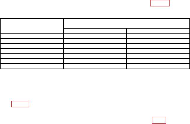
(5) Set OUTPUT LEVEL (dBm) switch to settings listed in table 4. Multimeter
will indicate within limits specified.
Table 4. Attenuator Accuracy
Test instrument
Multimeter
OUTPUT LEVEL
indications (V)
switch settings (dBm)
Min
Max
+10
2.36633
2.53557
-10
0.236633
0.253557
-20
0.073973
0.081110
-30
0.023125
0.025946
-40
0.007229
0.008300
-50
0.002260
0.002655
-60
0.000706
0.000849
(6) Set OUTPUT LEVEL (dBm) switch to 0.
(7) Adjust OUTPUT LEVEL (dBm) CAL control for a 0.774597 V ac indication
on multimeter.
(8) Adjust FREQUENCY Hz dial and frequency multiplier pushbuttons to values
listed in table 5 below. Multimeter will indicate within limits specified.
(9) Adjust OUTPUT LEVEL (dBm) CAL control fully cw (to detent).
b. Adjustments. Remove left side cover from TI and adjust R1423 (fig. 1) for 0.775 V ac
indication on multimeter (R).

