
TB 9-6625-2189-24
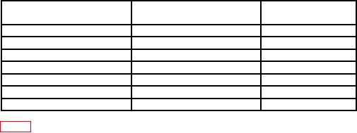
Table 7. A/D Converter Verification Test
Tolerance1
Test instrument
Input
indications
( digits)
0
.00000 V dc
2
-0.03
V dc
-30.000 mV dc
2
+0.03
V dc
+30.000 mV dc
2
-0.66
V dc
-0.6600 V dc
3
+0.66
V dc
+0.6600 V dc
3
-1.97
V dc
-1.97000 V dc
4
+1.97
V dc
+1.97000 V dc
4
1This
test is not considered a performance test; therefore, the specification listed in
table 2 will not apply.
b. Offset and Gain (R)
(1) Dc Voltage
(a) Disconnect calibrator from TI. Press VDC function pushbutton.
(b) When +00.0 is displayed, short INPUT HI and LO terminals. Press
TRIG/STORE pushbutton.
NOTE
When TRIG/STORE pushbutton is pressed, the TI display
field blanks while necessary calculations are being performed.
Do not change input voltage while the display is blank.
(c) When +190.0 mV DC is displayed, connect calibrator OUTPUT to TI
INPUT HI and LO terminals.
(d) Set calibrator for a +190 mV dc output. Allow approximately 10 seconds
for calibrator output stabilization, then press TI TRIG/STORE pushbutton.
(e) Repeat technique of (d) above for each successive prompted voltage
displayed by the TI, being careful to apply proper voltage and indicated polarity. The last
prompt should be +1000. V DC. Afterwards, the TI will begin taking readings in the 1000 V range.
(f) Set calibrator to STANDBY and press RESET pushbutton.
(2) Ac Voltage
(a) Press TI V function pushbutton.
(b) When 10.0 mV AC is displayed, connect ac divider (p/o calibrator)
between calibrator OUTPUT and TI INPUT HI and LO terminals.
(c) Set calibrator for a 10 V, 1 kHz output. (This will result in a 10 mV
input to TI.) Allow approximately 10 seconds for calibrator output stabilization, then press
TI TRIG/ STORE pushbutton.
(d) When 100.0 mV AC is displayed, remove ac divider from equipment
setup and set calibrator for a 100 mV, 1 kHz output. Allow approximately 10 seconds for
calibrator output stabilization, then press TI TRIG/STORE pushbutton.
11

