
TB 9-6625-2211-24
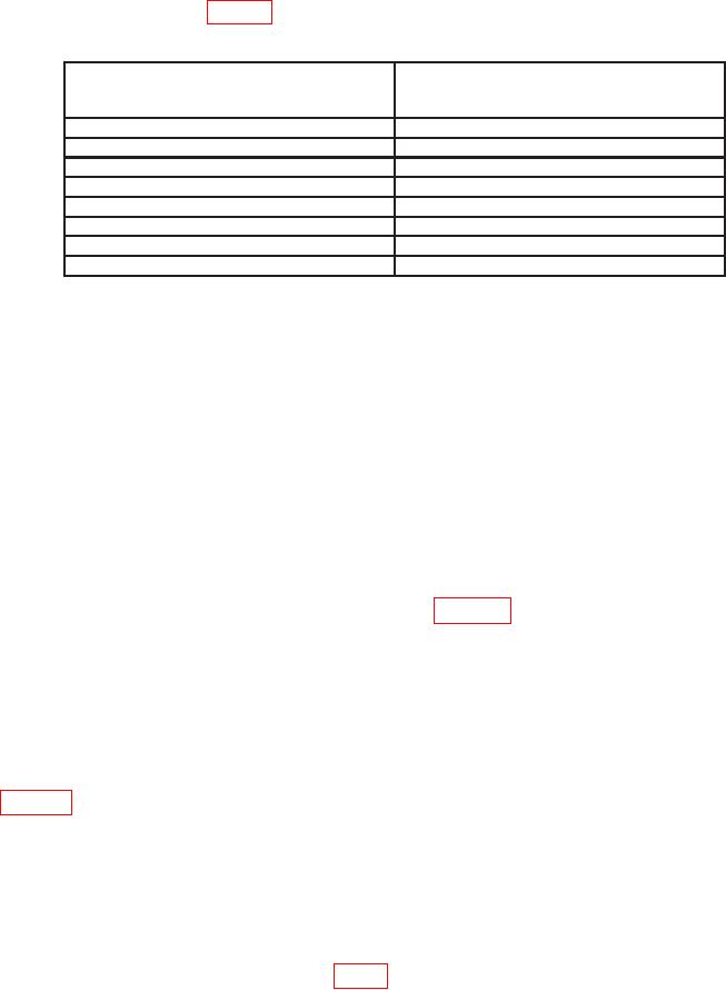
(17) Repeat technique of (16) above for REPLIES SUB PULSE POS SELECT
switch settings listed in table 9. The spacing will be within the limits specified.
Table 9. SUB Pulse POS
REPLIES SUB PULSE
Spacing
POS SELECT
(Ps)
switch settings
-.50
0.95
r0.02
-.35
1.10
r0.02
-.25
1.20
r0.02
-.15
1.30
r0.02
+.15
1.60
r0.02
+.25
1.70
r0.92
r.35
1.80
r0.02
r.50
1.95
r0.02
(18) Set REPLIES SUB PULSE SEL switch to A2.
(19) Set REPLIES SIF REPLY CODE switches to 2000 and REPLIES SUB
PULSE POS SELECT switch to VARY. Turn the REPLIES SUB PULSE POS VARY
control from fully ccw to fully cw while observing the pulse spacing on the oscilloscope. The
pulse spacing will vary from <5.0 to >6.6 Ps.
(20) Set REPLIES SUB PULSE POS SELECT switch to +.25.
(21) Set REPLIES SIF REPLY CODE switches to 7777.
Adjust oscilloscope
controls as necessary to view reply pulse train.
NOTE
The locations of the pulses in (22) through (27) below on the
oscilloscope can be determined using figure 5.
(22) Set REPLIES SUB PULSE SEL switch to A1 while observing oscilloscope
display. The 3d pulse will move.
(23) While observing oscilloscope display, set REPLIES SUB PULSE SEL switch
to C2. The C2 pulse will move.
(24) Repeat (23) above for REPLIES SUB PULSE SEL switch settings listed in
table 10. The pulse in the reply train that corresponds to the selected switch setting will move.
(25) Set REPLIES SUB PULSE POS SELECT switch to 0 and REPLIES
MODULATION SEL switch to I/P M1. Two reply pulse trains will be present on
oscilloscope display.
(26) Set REPLIES MODULATION SEL switch to I/P M2/3 and PRT SEL (USEC)
(500 USEC MIN) switches to 0600. The oscilloscope will display a reply pulse train
followed by a single pulse SP1 PULSE (fig. 5).
18

