
TB 9-6625-2211-24
NOTE
In (9) and (10) below, adjust oscilloscope time base controls as
necessary to obtain maximum resolution of the Channel 1
markers. Channel 1 and Channel 2 must be in ADD mode.
(9) Adjust signal generator No. 1 frequency controls until the center of the birdie is
added with the 1st timing marker (1085 MHz) as indicated on oscilloscope display. Signal
generator No. 1 display will indicate between 1084.9 and 1085.1 MHz. If not, perform b below.
(10) Repeat technique of (9) above for TI timing markers listed in table 13. If signal
generator No. 1 display indications are not within limits specified, use the technique of b
below and perform appropriate adjustment as listed in table 13.
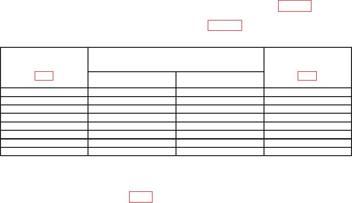
Table 13. RF Output Frequency Accuracy
Test
Signal generator No. 1
instrument
display indications
timing markers
(MHz)
Adjustment
Min
Max
(MHz)
(R)
1089
1088.9
1089.1
A11R21
1090
1089.9
1090.1
A11R26
1091
1090.9
1091.1
A11R31
1095
1094.9
1095.1
A11R36
11001
1099.7
1100.3
A11R41
1105
1104.7
1105.3
A11R46
1075
1074.7
1075.3
A11R6
1080
1079.7
1080.3
A11R11
1Set
SIG GEN FUNCTION switch to SWP r 15 MHz.
b. Adjustments. Adjust signal generator frequency controls for a display indication of
1085.00 MHz and adjust A11R16 (fig. 1) to align timing marker with center of birdie (R).
17. Output Power Accuracy
a. Performance Check
(1) Position controls as listed in 7 d. above.
(2) Zero and calibrate measuring receiver sensor module. Connect measuring
receiver sensor module input to TI SUM RF IN/OUT. Set measuring receiver to measure
frequency then tuned RF power.
(3) Set REPLIES MODULATION SEL switch to CW. Measuring receiver will
indicate 0 l dBm. If not, perform b below. Record measuring receiver indication.
(4) Set SIG GEN FUNCTION switch to SWP 5 MHz. Measuring receiver will
indicate within 1 dB of value recorded in (3) above.

