
TB 9-6625-2215-24
(7) Adjust function generator for 10 kHz and minimum output.
(8) Connect function generator output to TI A and B INPUT using termination and
tee connector.
(9) Set TI function switch to .1 s.
(10) Slowly increase function generator amplitude until TI indicates a stable count.
If function generator exceeds 25 mV, perform b (4) and (5) below.
b. Adjustments
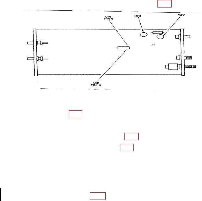
(1) Connect oscilloscope VERTICAL 1 input to U18 PIN 6 (fig. 2).
Figure 2. Test Instrument - (HP 5304B) - Bottom View.
(2) Adjust function generator frequency to 10 MHz and amplitude to 50 mV.
(3) Adjust A1 R20 (fig. 2) for a symmetrical waveform with minimum or no change
in duty cycle when SLOPE switch is changed from + to - and minimum or no change when
AC/DC switch is set to AC or DC.
(4) Connect oscilloscope input to U18 PIN 8 (fig. 2).
(5) Repeat (2) above and adjust A1 R19 (fig. 2) for a symmetrical waveform with
minimum or no change in duty cycle when SLOPE switch is changed from + to - and
minimum or no change when AC/DC switch is set to AC or DC.
27. Final Procedure
a. Deenergize and disconnect all equipment and reinstall protective cover on TI.
b. See manufacturer's manual for further maintenance procedures and attach
DA Label 163 stating Limited Cal to table 1 specifications.
Change 1

