
TB 9-6625-2233-35
12. Output Distortion
a. Performance Check
(1) Connect TI function outputs UNBALANCED to audio analyzer INPUT HIGH
using a 50 Ω feedthrough termination.
(2) Press CALIBRATION pushbutton (allow enough time to complete and verify
AUTOCALIBRATED is displayed) and then press RESET pushbutton.
(3) Press FREQUENCY pushbutton and enter 1000. Measure distortion using
standard distortion measurement technique. If total harmonic distortion is not <0.5% (-46 dBc),
perform b below.
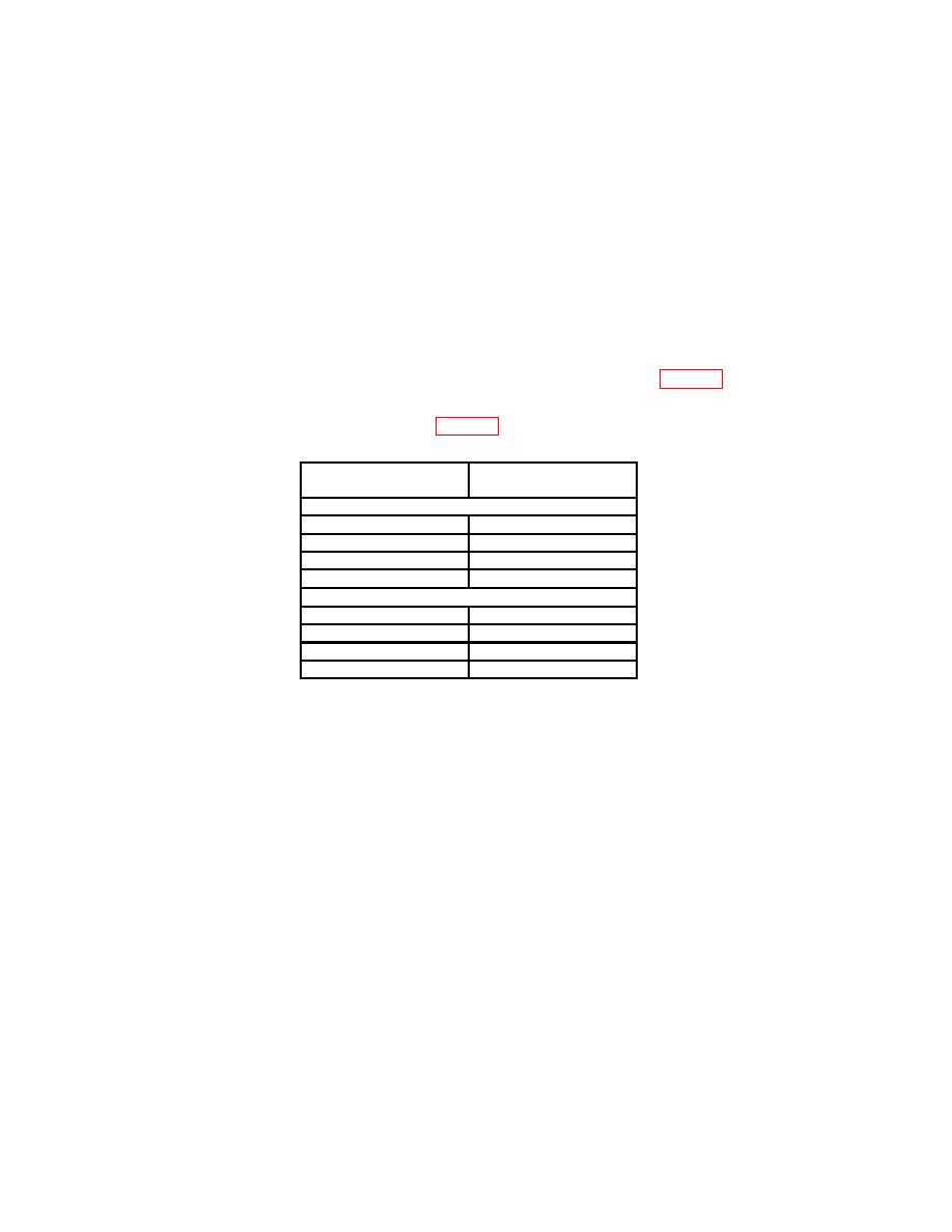
(4) Repeat (3) above substituting values from <10 V section of table 5.
(5) Press AMPLITUDE (until VPP is displayed) and enter 15.0. Repeat (3) above
substituting values from ≥10 V section of table 5.
Maximum total
Test instrument
harmonic distortion
frequency settings
<10 V
1.00
kHz
<0.5% (-46 dBc)
20.00
Hz
<0.5% (-46 dBc)
99.9
kHz
<0.5% (-46 dBc)
100.0
kHz
<1%
(-40 dBc)
≥10 V
1.00
kHz
<0.5% (-46 dBc)
20.00
Hz
<0.5% (-46 dBc)
99.9
kHz
<0.5% (-46 dBc)
100.0
kHz
<1%
(-40 dBc)
(6) Reduce outputs to minimum. Disconnect cable and 50 Ω feedthrough
termination from the audio analyzer INPUT HIGH and connect to tunable active filter input.
(7) Connect tunable active filter output to the audio analyzer INPUT HIGH.
(8) Press pushbuttons as listed in (a) through (h) below:
(a)
FREQUENCY.
(b)
1.
(c)
EXP.
(d)
3.
(e)
ENTER.
(f)
AMPLITUDE.
(g)
5.
(h)
ENTER.
(9) Set tunable active filter for a bandpass of 800 to 1200 Hz and repeat (3) above
substituting a distortion indication of <.1% (-60 dBc).
(10) Disconnect equipment setup.

