
TB 9-6625-2233-35
(5) Reduce TI output to minimum. Set the measuring receiver to measure power.
(6) Connect measuring receiver power sensor to CALIBRATOR RF POWER
connector and zero and cal the measuring receiver. Then disconnect measuring receiver
power sensor from CALIBRATOR RF POWER connector.
(7) Set the measuring receiver to measure power in millivolts.
(8) Disconnect TI UNBALANCED output from multimeter and connect
UNBALANCED output to measuring receiver power sensor (do not use the 50 Ω
feedthrough termination).
(9) Press pushbuttons as listed in (a) through (h) below:
(a)
(b)
100.
(c)
EXP.
(d)
3.
(e)
ENTER.
(f)
AMPLITUDE.
(g)
.099.
(h)
ENTER.
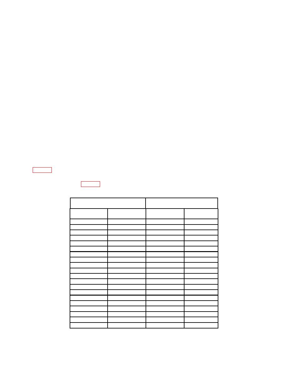
(10) Measuring receiver will indicate within minimum maximum limits as listed in
(11) Repeat technique of (9) (a) through (h) and (10) above substituting settings and
indications listed in table 7.
Measuring receiver indications
Test instrument
(mV)
Output
(V p-p)
Min
Max
100
kHz
.099
33.2
36.8
100
kHz
.2
67.17
74.24
100
kHz
.999
338
368
100
kHz
2
675
739
100
kHz
15
5086
5518
999.9
kHz
.099
33.2
36.8
999.9
kHz
.2
67.17
74.24
999.9
kHz
.999
338
368
999.9
kHz
2
675
739
999.9
kHz
15
5086
5518
1
MHz
.099
32.9
37.1
1
MHz
.2
66.46
74.94
1
MHz
.999
335
372
1
MHz
2
668
746
1
MHz
15
5034
5571
4.999 MHz
.099
32.9
37.1
4.999 MHz
.2
66.46
74.94
4.999 MHz
.999
335
372
4.999 MHz
2
668
746
4.999 MHz
15
5034
5571
17

