
TB 9-6625-2233-35
(12) Reduce TI output to minimum. Disconnect UNBALANCED output from
measuring receiver power sensor and connect UNBALANCED output to oscilloscope
Vertical 1 input using a 50 Ω feedthrough termination.
(13) Press pushbuttons as listed in (a) through (h) below:
(a)
(b)
5.
(c)
EXP.
(d)
6.
(e)
ENTER.
(f)
AMPLITUDE.
(g)
.099.
(h)
ENTER.
(14) Set oscilloscope Vertical 1 inputs for DC Coupling, 1MΩ Input, scaling for
approximately 4 or 5 divisions displayed, sweep speed for approximately 4 or 5 cycles
displayed and volts pk-pk measurement.
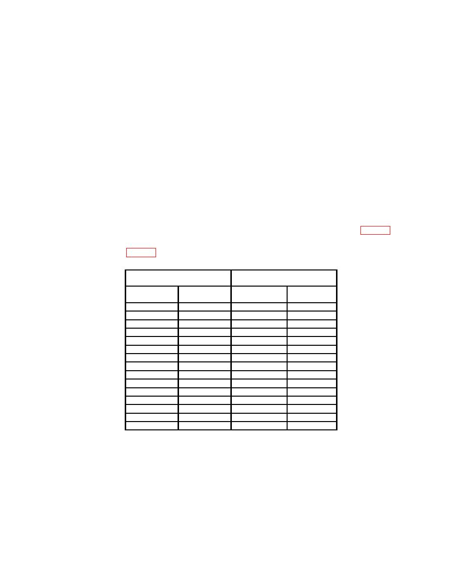
(15) Oscilloscope will indicate within minimum maximum limits as listed in table 8.
(16) Repeat technique of (13) through (15) above substituting settings and
indications listed in table 8.
Oscilloscope indications
Test instrument
(V p-p)
Output
Min
Max
(V p-p)
5
MHz
.099
.086
.112
5
MHz
.2
.174
.226
5
MHz
.999
.877
1.12
5
MHz
2
1.75
2.25
5
MHz
15
13.2
16.8
15.99 MHz
.099
.086
.112
15.99 MHz
.2
.174
.226
15.9 MHz
.999
.877
1.12
15.99 MHz
2
1.75
2.25
15.99 MHz
15
13.2
16.8
19.99 MHz
.099
.068
.130
19.99 MHz
.2
.138
.262
19.99 MHz
.999
.697
1.30
19.99 MHz
2
1.39
2.61
19.99 MHz
15
10.5
19.5
b. Adjustments. No adjustments can be made.
14. Triangle Wave Amplitude
a. Performance Check
(1) Connect UNBALANCED output to multimeter input using 50 Ω feedthrough termination.
(2) Press pushbuttons as listed in (a) through (i) below:

