
TB 9-6625-2235-24
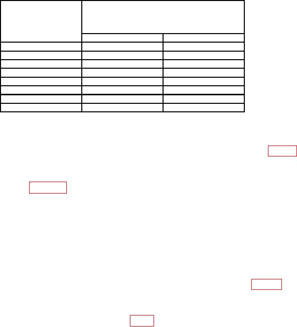
Table 9. Log Fidelity Check
Variable
Multimeter indication
attenuator
(plus offset recorded in (7) above
10 dB step
(MV)
control settings
(dB)
Min
Max
0
799
801
10
697
703
20
596
604
30
496
504
40
395
405
50
294
306
60
193
207
70
92
108
(20) Set REFERENCE LEVEL switch to -50 dBm and press LIN pushbutton in.
(21) Set variable attenuator 10 dB step control to 0 dB and adjust A14R34 (fig. 13)
for a multimeter indication of 800 mV 1 mV (plus offset voltage recorded in (7) above) (R).
(22) Set REFERENCE LEVEL switch and variable attenuator 10 dB step control to
settings as listed in table 10. If multimeter indication is not within specified limits,
perform adjustment listed.
(23) Set REFERENCE LEVEL switch to -50 dBm and press 1 dB/DIV pushbutton in.
(24) Set variable attenuator 10 dB step control to 0 dB and adjust signal generator
RF output controls for a multimeter indication of 800 mV, 1 mV (plus offset voltage
recorded in (7) above).
(25) Set variable attenuator 10 dB step control to 40 dB.
(26) Set REFERENCE LEVEL switch to -90 dBm and adjust A14R121 (fig. 13) for
a multimeter indication of 800 mV, 3 mV (plus offset voltage recorded in (7) above) (R).
(27) Return A12S1TEST/NORM switch (located on A12 board) to NORM. Remove
test cable and reconnect W7 (red) cable to A9J1 (fig. 1).
NOTE
Adjustment steps (28) through (52) below are used for SN
prefix 2142A and below.
(28) Position controls as listed in (a) through (e) below:
(a) FREQ SPAN/DIV switch to 1 MHz.
(b) RESOLUTION BW switch to 300 kHz.
(c) OPTIMUM INPUT switch to -30 dBm.
33

