
TB 9-6625-2239-24
(5) Rotate oscilloscope calibrator knob located below EDIT FIELD pushbutton to
adjust output for 0.0% indication on err display. Adjust R118 (fig. 2) for 6 divisions of
vertical display. If R118 does not adjust to 6 divisions, adjust R118 to midrange; then
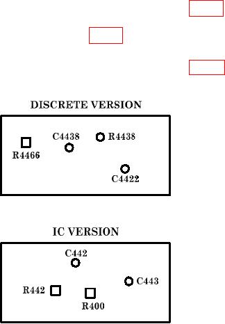
adjust R400 (R4466 for DISCRETE VERSION) (fig. 4) for 6 divisions of vertical display (R).
(6) Rotate oscilloscope calibrator knob located below EDIT FIELD pushbutton to
adjust output for 0.0% indication on err display. Adjust R218 (fig. 2) for 6 divisions of
vertical display (R).
Figure 4. Tektronix, Type 465 and 465 with options - A5 circuit board.
9. Timing
NOTE
For oscilloscopes with digital multimeters attached, refer to the
calibration section of the manufacturer's manual for the digital
a. Performance Check
(1) Press VERT MODE CH 1 pushbutton to on (in), set A AND B TIME/DIV
switches to 1 ms, and VOLTS/DIV switch to .5.
(2) Connect oscilloscope calibrator SOURCE/MEASURE CHAN 1 to TI CH 1
using a 50 feedthrough termination.
(3) Set oscilloscope calibrator MARKER output for 1 ms.
(4) Adjust TI horizontal POSITION control to align 1st marker on 1st vertical
graticule line.
(5) Rotate oscilloscope calibrator knob located below EDIT FIELD pushbutton for 1
marker per division. If oscilloscope calibrator err display readout does not indicate within
2%, perform b (1) below.

