
TB 9-6625-2239-35
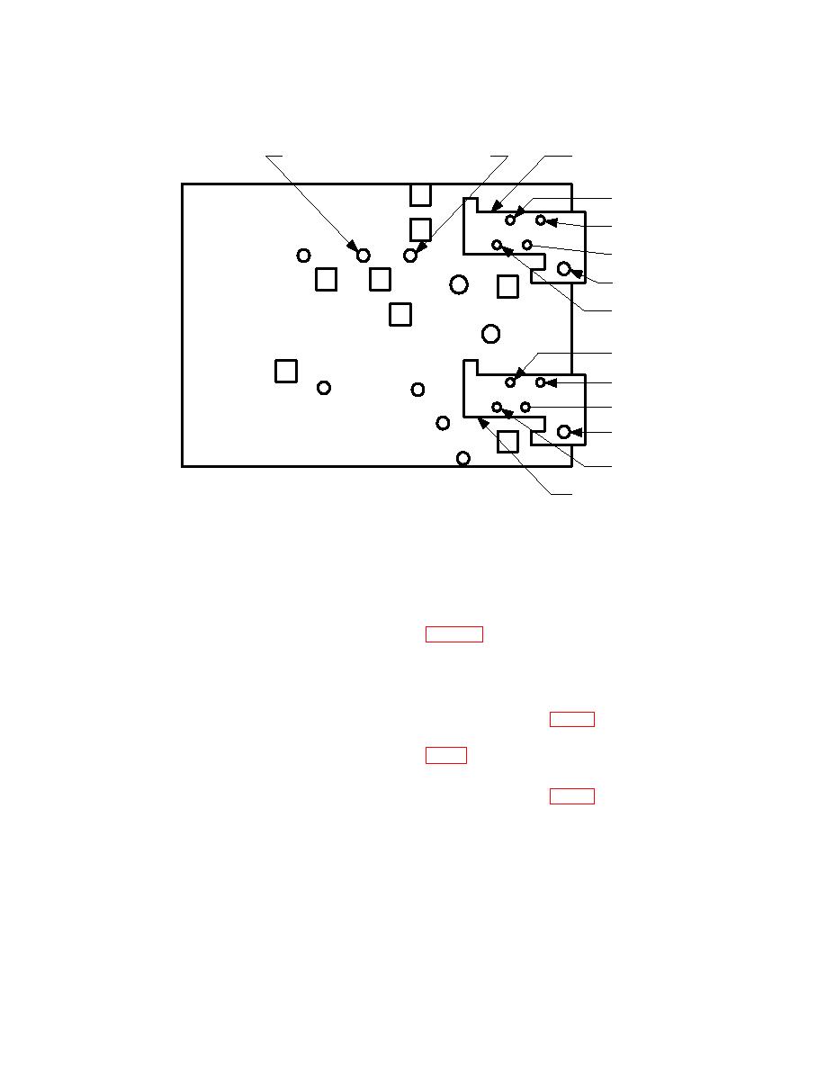
C122
C105
CHANNEL
1
R118
C13
C11
R105
C10
C149
R122
R149
C1
C33
R25
C12
R218
C27
C63
R249
C61
C205
C60
C249
C83
C51
R75
C77
C62
CHANNEL
2
(13) Repeat technique of (7) through (12) above for CH 2. If oscilloscope calibrator
err display does not indicate within 3% (2% for AN/USM-425(V)l), perform b(2) for
Tektronix, Type 465B; b(4) for AN/USM-425(V)l; or b(6) for Tektronix, Type 465.
(14) Repeat technique of (12) above for CH 2 using TI switch settings and
oscilloscope calibrator output voltage listed in table 4. Oscilloscope calibrator err display
will indicate 3% (2% for AN/USM-425(V)l) for each setting.
b. Adjustments
(1) Rotate oscilloscope calibrator knob located below EDIT FIELD pushbutton to
adjust output for 0.0% indication on err display. Adjust R1482 (fig. 3) for 6 divisions of
vertical display. If R1482 does not adjust to 6 divisions, adjust R1482 to midrange; then
adjust R2025 (R2005 for SN B030000 and below) (fig. 3) for 6 divisions of vertical display (R).
(2) Rotate oscilloscope calibrator knob located below EDIT FIELD pushbutton to
adjust output for 0.0% indication on err display. Adjust R1882 (fig. 3) for 6 divisions of
vertical display (R).
8

