
TB 9-6625-2240-24
(2) Adjust horizontal POSITION control to align 1st time marker with 1st graticule
line. Rotate oscilloscope calibrator knob located below EDIT FIELD output to obtain 1
marker per division on TI. Oscilloscope calibrator err display will be within limits specified
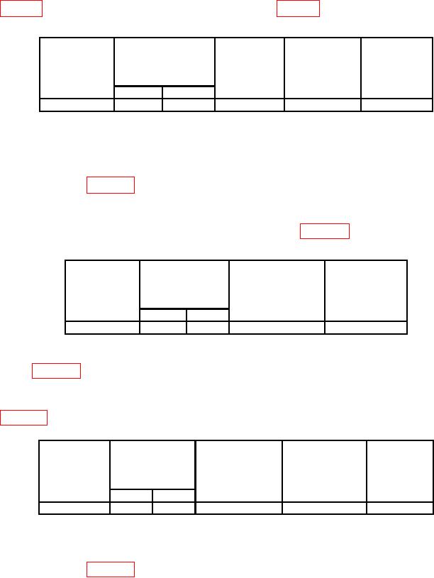
Table 9. Delay Time and Differential Measurement
Test
Oscilloscope
Oscilloscope
Test instrument
instrument
Test
calibrator err
TIME/DIV
calibrator
VOLTS/DIV
instrument
display limits
MARKER
switch settings
switch
adjustments
(%)
output
settings
A
B
10 s
1 s
1 s
b(1)
.5
2
(3) Press HORIZ DISPLAY B DLY'D pushbutton (in).
(4) Set X10 MAG pushbutton (out).
(5) Set TI VOLTS/DIV, TIME/DIV switch settings and oscilloscope calibrator
output as listed in table 10.
(6) Adjust horizontal POSITION control to align start of sweep with center vertical
graticule line. Leading edge of displayed time marker will be aligned with the center
vertical graticule line; if not, perform adjustment listed in table 10.
Table 10. Delay Time and Differential Measurement
Test
Oscilloscope
Test instrument
instrument
Test
TIME/DIV
calibrator
VOLTS/DIV
instrument
switch settings
MARKER output
switch
adjustment
settings
settings
A
B
10 s
0.1 s
10 s
b(2)
.5
(7) Set TI VOLTS/DIV, TIME/DIV switch and oscilloscope calibrator output as
listed in table 11.
(8) Rotate DELAY TIME POSITION dial to 9.00. Leading edge of displayed time
marker will be aligned with center vertical graticule line; if not, perform adjustment listed
in table 11.
Table 11. Delay Time and Differential Measurement
Test instrument
Test
Oscilloscope
Test instrument
DELAY TIME
Test
instrument
TIME/DIV
calibrator
POSITION
VOLTS/DIV
instrument
MARKER
switch settings
dial limits
switch
adjustment
output settings
()
settings
A
B
10 s
0.1 s
10 s
b(3)
.5
.05
(9) Rotate DELAY TIME POSITION dial to 1.00.
(10) Set TI VOLTS/DIV, TIME/DIV switch settings and oscilloscope calibrator
output as listed in table 12.
12

