
TB 9-6625-2240-24
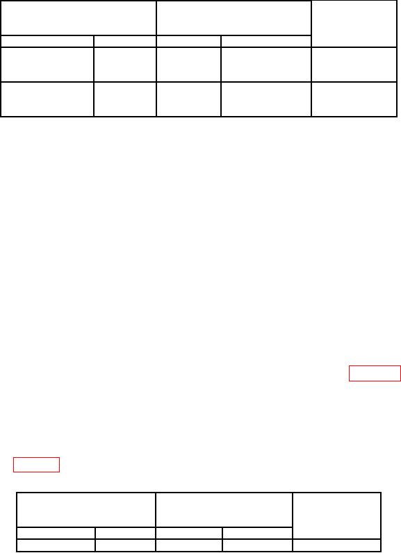
Table 20. Bandwidth Measurement Setup
Oscilloscope calibrator LEVEL
Test instrument
Test instrument
SINE
amplitude limits
switch settings
output settings
(divisions)
(≥)
VOLTS/DIV
TIME/DIV Amplitude
5m
0.1 ms
30 mV pp
50 kHz
4.2
to
200 MHz
10 m
0.1 ms
60 mV pp
50 kHz
4.2
(Tektronix, Type
to
475A)
250 MHz
NOTE
To perform the step below, press EDIT FIELD pushbutton as
required to place underline under one of the frequency digits.
(34) Rotate oscilloscope calibrator knob below EDIT FIELD pushbutton to sweep
oscilloscope from 50 KHz to 200 MHZ while observing displayed waveform amplitude on TI
crt. Displayed waveform will be 4.2 divisions or greater in amplitude throughout entire
range to 200 MHz (250 MHz for Tektronix, Type 475A).
b. Adjustments. No further adjustments.
12. Calibrator
a. Performance Check
(1) Connect TI CALIBRATOR (front panel) to TI CH1.
(2) Press VERT MODE CH1 pushbutton (in).
(3) Press oscilloscope calibrator VOLTAGE pushbutton to illuminate green LED.
(4) Set TIME/DIV and CH1 VOLTS/DIV switches as listed in table 21. Adjust
CH1 VOLTS/DIV VAR control for 6 divisions of vertical deflection on TI.
(5) Remove connection at TI CALIBRATOR and connect to oscilloscope calibrator
CHAN 1.
(6) Rotate oscilloscope calibrator knob below EDIT FIELD pushbutton to adjust for
6 divisions of vertical deflection on TI. Oscilloscope calibrator err display will indicate as
specified in table 21, if not perform b below.
Table 21. Test Instrument Calibrator Output Check
Oscilloscope calibrator
Test instrument
VOLTAGE
Err
Test instrument
output settings
display limits
switch settings
VOLTS/DIV
TIME/DIV Amplitude
(%)
50 mV
.2 ms
300 mV pp
1 kHz
1

