
TB 9-6625-2247-40
(34) Connect synthesized signal generator RF output cable to INPUT 1. RED LED
(fig. 1) will be off.
NOTE
If techniques (32) through (34) above fail,
repeat techniques (29) through (31) above.
11. Input 1 Sensitivity Test (18 to 40 GHz)
a. Performance Check
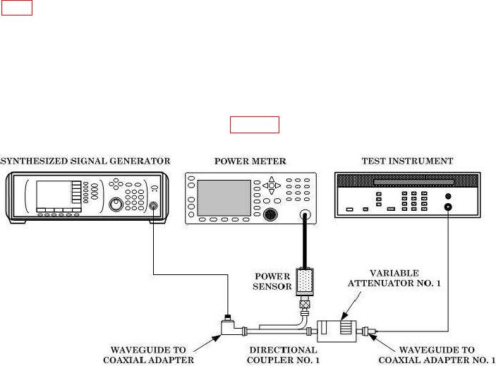
(1) Connect equipment as shown in figure 4.
Figure 4. Sensitivity test (18 to 26.5 GHz) - equipment setup.
(2) Ensure AUTO key on FUNCTION DATA keyboard is pressed.
(3) Set variable attenuator No. 1 to 0 dB.
controls for a -10 dBm indication on power meter.
(5) Slowly increase variable attenuator No. 1 attenuation until TI loses stable count.
(6) Slowly decrease variable attenuator No. 1 attenuation until TI just begins to
indicate a stable count.
(7) Add 10 dB (directional coupler No. 1 coupling factor) to power meter indication.
Record sum.
(8) Subtract 0.5 dB (waveguide to coaxial adapter insertion loss (max)) from
variable attenuator No. 1 correction chart value. Record difference.
(9) Subtract difference recorded in technique (8) above from sum recorded in
technique (7) above. If the difference is not at least -25 dBm minimum, prepare a test
report using the actual sensitivity value for test frequency.

