
TB 9-6625-2251-35
NOTE
If TI does not perform within limits specified in this paragraph,
perform adjustments as indicated in Section IV.
a. Select: TRIGGER MODE and verify AUTO is on; if not, press Set: AUTO to on.
b. Rotate TI CH 1 VOLTS/DIV knob to set CH1 for 2 mV indication in upper left
portion of crt. Select CURSOR FUNCTION and set VOLTS to on.
c. Rotate CURSOR DELAY knob and align segmented cursor 3 divisions below crt
horizontal centerline.
e. Select: CURSOR SELECT and rotate CURSOR DELAY knob to align next
segmented cursor 3 divisions above crt horizontal centerline. Display will indicate within
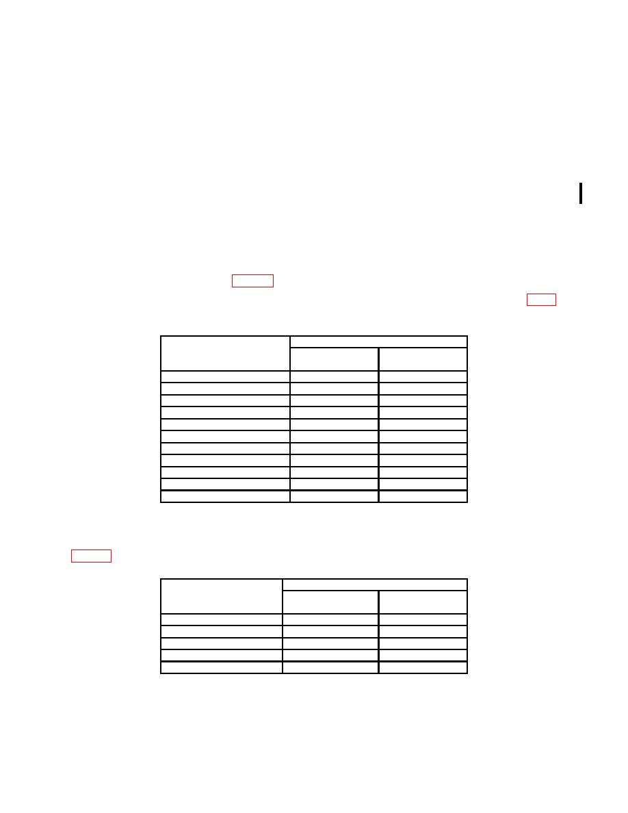
Min/Max indications shown in table 3.
3.
Range
Indications
VOLTS/DIV
settings
Min
Max
2mV
11.88 mV
12.12 mV
5mV
29.7 mV
30.3 mV
10mV
59.4 mV
60.6 mV
20mV
118.8 mV
121.2 mV
50mV
297 mV
303 mV
100 mV
594 mV
606 mV
200 mV
1.188 V
1.212 V
500 mV
2.970 V
3.030 V
1V
5.94 V
6.06 V
2V
11.88 V
12.12 V
5V
29.7 V
30.3 V
g. Select: VERTICAL MODE, set: CH 2 to on, and set: CH1 to off.
h. Repeat technique of b through e above for CH 2, using settings and indications in
table 4 below.
Range
Indications
VOLTS/DIV
settings
Min
Max
2
mV
11.88
mV
12.12
mV
5
mV
29.7 mV
30.3 mV
10 mV
59.4 mV
60.6 mV
20 mV
118.8 mV
121.2 mV
50 mV
297 mV
303 mV
CHANGE 1
PIN: 070750-001

