
TB 9-6625-2251-35
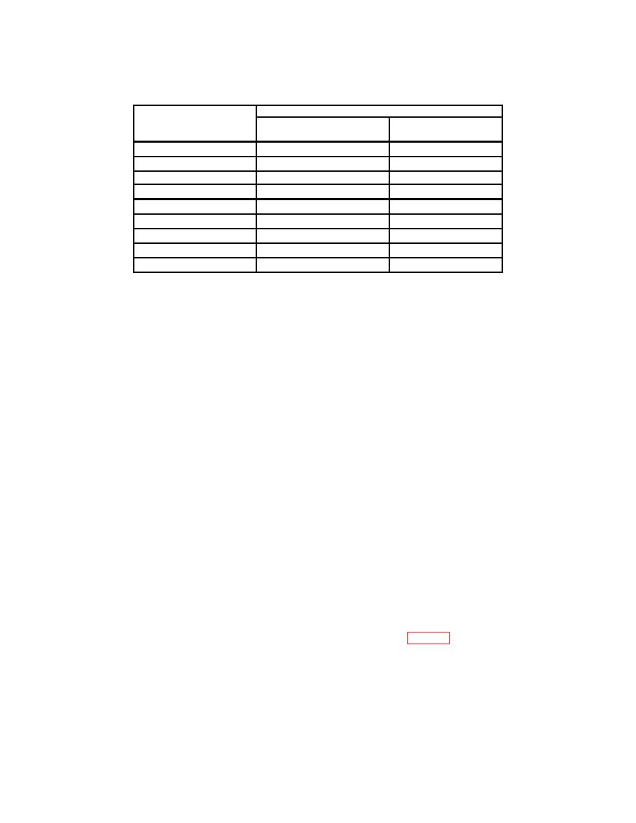
Table 8. Channel 2 Vertical Gain Accuracy - Continued
Oscilloscope calibrator
CH2 VOLTS/DIV
VOLTAGE
Err display
settings
settings
(%)
10 mV
40 mV
2.0
20
mV
80
mV
2.0
50 mV
200 mV
2.0
100 mV
400 mV
2.0
200 mV
800 mV
2.0
500 mV
2V
2.0
1V
4V
2.0
2V
8V
2.0
5V
20
V
2.0
k. Select: VERTICAL MODE, set: CH 1 to on and set: CH 2 to off.
l.
Set oscilloscope calibrator output to standby.
10. Bandwidth Accuracy
NOTE
If TI does not perform as specified, perform adjustments as
indicated in Section IV.
a. Select: CH 1 COUPLING/INVERT and set: 50 Ohm to on. Verify DC is set to on.
Adjust CH 1 POSITION control and align cursor on extreme left of crt with center
horizontal graticule line.
b. Select: TRIGGER MODE then set: AUTO.
c. Rotate CH 1 VOLTS/DIV knob to set CH1 for a 5 mV indication on crt. Adjust
HORIZONTAL A AND B SEC/DIV controls for 5 s indications on crt.
amplitude for 6 divisions peak-to-peak signal on TI crt. Adjust TRIGGER LEVEL control
as necessary to obtain a stable display.
to 4.2 divisions. Adjust TRIGGER LEVEL control and HORIZONTAL A AND B
150 MHz or greater.
frequency will be within tolerance listed.

