
TB 9-6625-2259-24
(3) Press POWER pushbutton to ON position.
(4) Press RESET key and allow TI to warm up for 30 minutes.
(5) Connect measuring receiver power sensor to RF OUTPUT 50 .
(6) Press FREQUENCY RANGE CW F1 key and set F1 M3 display to 2.050 GHz
by pressing 2.05 with DATA ENTRY keys and then by pressing GHz/dBm/SEC DATA
ENTRY key.
(7) Configure measuring receiver to measure frequency and allow measuring
receiver to acquire carrier frequency.
(8) Configure measuring receiver to measure RF power.
(9) Remove TI top cover.
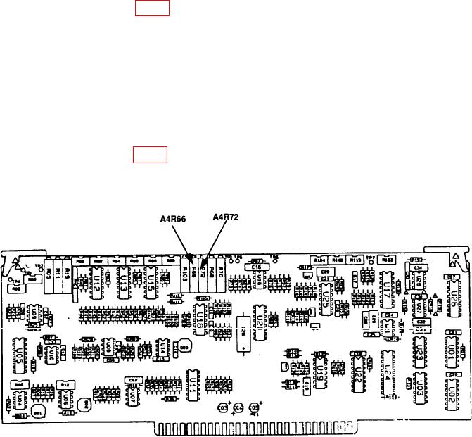
(10) Adjust A4R66 (fig. 4) for a measuring receiver RF power display indication
between +6.9 and +7.1 dBm.
(11) Replace TI top cover.
NOTE
Wait 5 minutes before proceeding to (12) below.
(12) Press LEVEL key and set LEVEL display to -2.9 dBm by pressing -2.9 with
DATA ENTRY keys and then by pressing GHz/dBm/SEC DATA ENTRY key.
(13) Remove TI top cover.
(14) Adjust A4R72 (fig. 4) for a measuring receiver RF power display indication
between -2.8 and -3.0 dBm (R).
(15) Replace TI top cover.
Figure 4. A1A4A4 component location diagram.
19

