
TB 9-6625-2264-24
b. Adjustments
NOTE
TI low light level adjustments may affect TI high light level
indications. It may be necessary to make adjustments for best
compromise.
(1) Remove GOGGLE SWITCH ASSEMBLY (fig. 2) using tamper-proof bit.
NOTE
Temporarily install GOGGLE SWITCH ASSEMBLY (fig. 2)
after making adjustment.
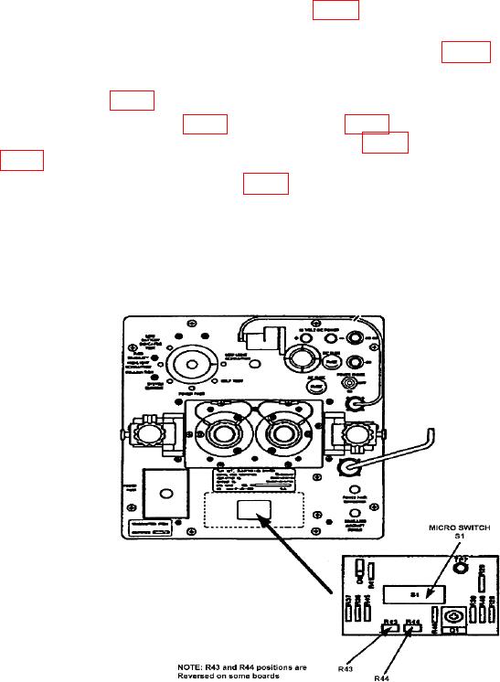
(2) Adjust R43 (fig. 3) for a 4.47 mV dc multimeter indication (R).
indication (R). Temporarily install goggle switch assembly (fig. 2) with ANVIS/NVG goggle
switch (fig. 2) in the down position.
(4) Install goggle switch assembly (fig. 2) using tamper proof bit.
9. Final Procedure
a. Deenergize and disconnect all equipment.
b. Annotate and affix DA label/form in accordance with TB 750-25.
Figure 3. TS-3895A/UV - adjustment locations.

