TB 9-6625-2274-50
n.
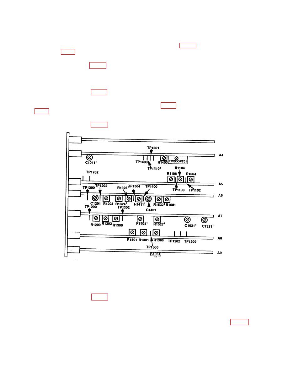
Connect multimeter positive lead to
A6TP1304 (fig. 1) and
negative lead to
o.
Adjust A6Rl325 (fig. 1) for a
multimeter indication of
-3.9809 V dc
.0.0003 V.
p. Press CONTINUE pushbutton. Display will indicate DAC 1.
q.
Adjust A6R1324 (fig. 1) for a
multimeter indication of
-6.7114 V dc
0.001 V.
r.
Connect multimeter positive lead A7TP1200 (fig. 1) and
negative lead to
A7TP1302
s.
Adjust A7R1202 (fig. 1) for a
multimeter indication of
-5.25 V dc
0.05 V.
1Indicates
test point or adjustments are located below top edge of board.
Figure 1. Test point and adjustment locations.
t. Press CONTINUE pushbutton. TI display will indicate HEAD.
u.
Adjust A7R1300 (fig. 1) for a
multimeter indication of
+5.25 V dc
0.05V.
Press CONTINUE pushbutton.
Display will
indicate DELY.
w. Connect TRIGGER OUTPUT to
oscilloscope CH 1.
Connect A7TP1200 (fig. 1) to
oscilloscope CH 2 using X10 probe. Acquire signal using oscilloscope. Set oscilloscope
16