
TB 9-6625-2278-24
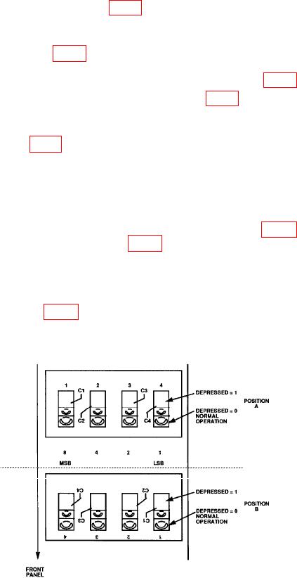
(4) Locate service switch A3S1 (fig. 1) (located on A3 board).
NOTE
Service switch will be either located on TI in POSITION A or
POSITION B (fig. 1).
(5) Note position of all four switches of service switch A3S1 (fig. 1).
(6) Place all four switches of service switch A3S1(fig. 1) into test position.
NOTE
Test position will be opposite to switch positions now displayed
on A3S1 (fig. 1) service switch.
(7) Press LINE switch to ON position.
NOTE
TI display will indicate _ _ _ _ _.
(8) Connect multimeter (dc mode) negative lead to A5TP2 (fig. 2) and then connect
digital multimeter positive lead to A5TP8 (fig. 2)
(9) Record multimeter indication.
(10) Enter multimeter indication recorded in (9) above into power meter by pressing
five digits (four decimal places) with TI keyboard and then by pressing ENTER key.
(11) Adjust A5R61 (fig. 2) for a TI display indication centered as close as possible to
zero (R).
Figure 1. A3S1 service switch.
6

