
TB 9-6625-2278-24
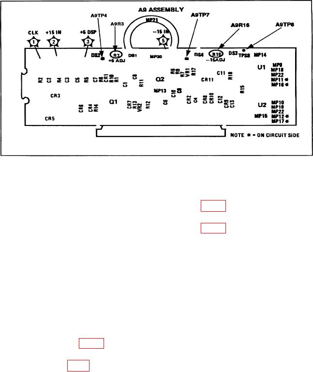
Figure 5. Power supply component location.
NOTE
Disregard sign of value measured in (5) below.
(5) Connect multimeter positive lead to A9TP7 (fig. 5). If multimeter does not
indicate within 0.05 V dc of value recorded in (4) above, perform b (l) below.
(6) Connect multimeter positive lead to A9TP4 (fig. 5).
If multimeter does not
indicate between 4.95 and 5.05 V dc, perform b (2) below.
(7) Press LINE switch to OFF position.
(8) Tighten screws that secure A3 CPU assembly.
(9) Replace TI top and bottom covers.
(10) Press LINE switch to ON position.
b. Adjustments
NOTE
Disregard sign of value measured in (1) below.
(1) Adjust A9Rl6 (fig. 5) for a digital multimeter indication within 0.05 V dc of
value recorded in (4) above (R).
(2) Adjust A9R3 (fig. 5) for a digital multimeter indication between 4.95 and 5.05 V dc (R).
15

