
TB 9-6625-2280-35
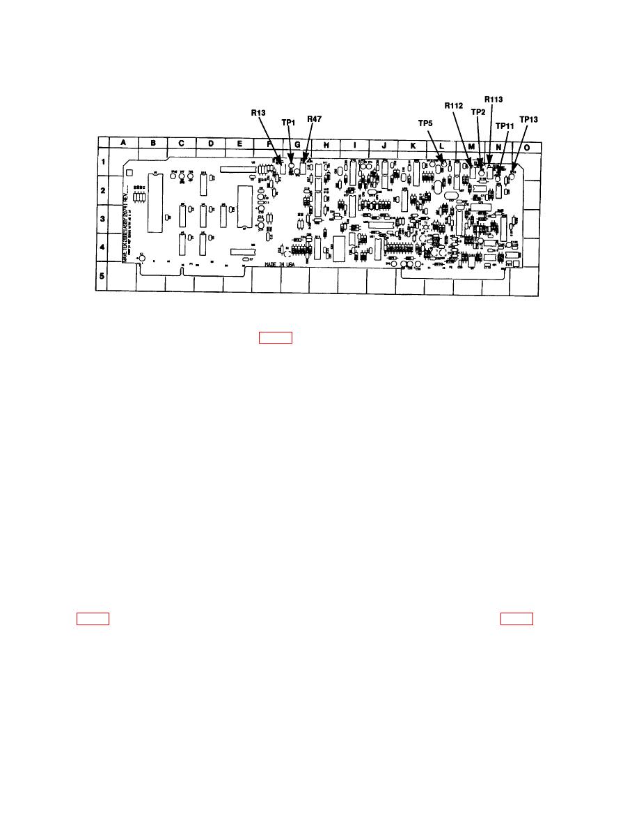
(3) Adjust A6R13 (A7R13) (fig. 3) for a multimeter indication between 9.997 and
10.003 V dc (R).
(4) Repeat (1) through (3) above for A7 board.
(5) Disconnect multimeter leads from TI.
NOTE
Perform first equipment hookup and adjustments on A6 board
for (6) through (17) below and, when instructed by text in (18)
below, perform equipment hookup and adjustments on A7
board.
(6) Press TI keys as listed in (a) through (d) below:
(a)
MENU key (two times).
(b)
F2 key.
(c)
20 using number keys.
Any UNITS key (nS or S or mS key).
(d)
(7) Connect SYNC OUTPUT (rear panel) to oscilloscope channel 2 input and set
this input as an external trigger on oscilloscope.
(8) Connect oscilloscope channel 1 input LO (common) lead to A6TP11 (A7TP11)
(9) Connect pulse generator output to TRIG INPUT on TI rear panel.
(10) Set pulse generator controls for a pulse signal with 5 V amplitude (TTL), 10 s
pulse width, and a repetition rate of 1 kHz.
(11) Press TI keys as listed in (a) through (c) below:
(a) PEAK key.
(b) MENU key.
15

