
TB 9-6625-2289-24
(4) Adjust calibrator voltage output controls for a TI meter indication specified in
(5) Repeat technique of (4) above for remaining RANGE settings listed in table 3.
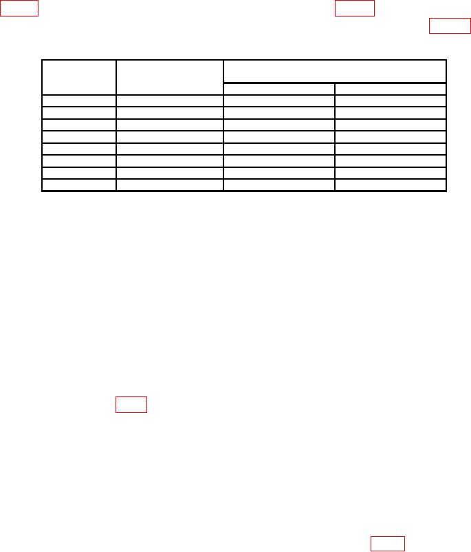
Table 3. Range Accuracy and Linearity
Test instrument
RANGE
meter indications
Calibrator indications
settings
(V)
Min
Max
.001
.001
.85
mV
1.15
mV
.003
.003
2.7
mV
3.3
mV
.01
.01
9.0
mV
11.0
mV
.03
.03
27.0
mV
33.0
mV
.1
.1
90.0
mV
110.0
mV
.3
.3
.270
V
.330
V
1
1
.9
V
1.1
V
3
3
2.7
V
3.3
V
(6) Set calibrator to standby.
(7) Disconnect TI RF probe from calibrator output.
b. Adjustments
NOTE
Ensure calibrator frequency controls are set for 50 kHz output.
(1) Connect TI RF probe to calibrator WIDEBAND OUTPUT.
(2) Set RANGE switch to 1.0.
(3) Adjust calibrator voltage output controls for a TI meter indication of 1.0 V ac.
(4) Connect frequency counter low lead to TI chassis.
(5) Connect frequency counter high lead to TI A5E1.
(6) Adjust R2 (fig. 1) for a frequency counter indication between 92 and 96 Hz (R).
(7) Disconnect TI from frequency counter and calibrator.
(8) Set TI RANGE switch to .001 VOLTS.
(9) Disconnect TI RF probe from calibrator.
(10) Zero TI meter with ZERO control.
NOTE
If necessary, repeat 7 g through i above.
(11) Set TI RANGE switch to .3 VOLTS and adjust R34 ZERO (fig. 1) for TI meter
indication of 0.
(12) Set RANGE switch to 3.0 VOLTS.
5

