
TB 9-6625-2293-24
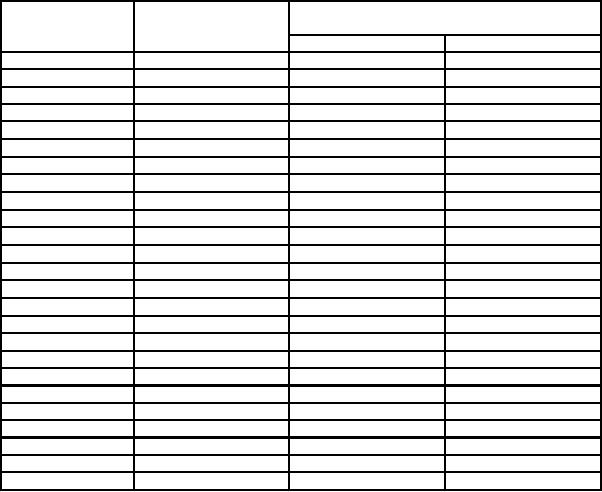
Table 10. A SWP Cursor Timing
Oscilloscope
Test instrument
Test instrument
Δt readout indications
A SWP/SEC/DIV
calibrator
switch settings
output
Min
Max
5 ns
5
nS/D
39.65 ns
40.35 ns
10 ns
10
nS/D
79.30 ns
80.70 ns
20 ns
20
nS/D
158.6 ns
161.4 ns
50 ns
50
nS/D
396.5 ns
403.5 ns
.1 μS/D
100 ns
793.0 ns
807.0 ns
.2 μS/D
200 ns
1586.0 ns
1614.0 ns
.5 μS/D
500 ns
3965.0 ns
4035.0 ns
1 μs
μS/D
7.93 μs
8.07 μs
1
2 μs
μS/D
15.86 μs
16.14 μs
2
5 μs
μS/D
39.65 μs
40.35 μs
5
10 μs
μS/D
79.30 μs
80.70 μs
10
20 μs
μS/D
158.60 μs
161.40 μs
20
50 μs
μS/D
396.5 μs
403.5 μs
50
100 μs
793.0 μs
807.0 μs
.1 mS/D
1586.0 μs
200 ms
.2 mS/D
1614.0 us
500 μs
μs
μs
.5 mS/D
3965
4035
1 ms
1
mS/D
7.930 ms
8.070 ms
2 ms
2
mS/D
15.860 ms
16.140 ms
5 ms
5
mS/D
39.65 ms
40.35 ms
10 ms
10
mS/D
79.30 ms
80.70 ms
20 ms
20
mS/D
158.60 ms
161.40 ms
50 ms
50
mS/D
396.5 ms
403.5 ms
100 ms
.1 S/D
793.0 ms
807.0 ms
200 ms
.2 S/D
1579
ms
1622
ms
500 ms
.5 S/D
3945
ms
4055
ms
(33) Set A SWP SEC/DIV switch to 10 ns and B SWP SEC/DIV switch to 5 ns
(knob out).
(34) Press Δt pushbutton to off for DLY readout.
(35) Press Xl0 MAG pushbutton to on.
(36) Press A/B TRIGGER pushbutton for B TRIGGER.
(37) Set TRIGGER MODE switch down to RUN AFT DLY.
(38) Change oscilloscope calibrator MARKER mode output to 10 nS/D.
(39) Set VOLTS/DIV switch as required for a display of 3 to 6 divisions and adjust
ΔREF OR DLY POS control for DLY 10.64 ns.
(40) Adjust TRIGGER LEVEL control as required for a stable display.
(41) Adjust horizontal POSITION control cw until the trace stops moving, then ccw
to display leading edge of the 2d time marker near graticule center.
(42) Change oscilloscope calibrator MARKER mode output to 5 nS/D.
(43) Press Δt pushbutton to obtain Δt display and push in SEC/DIV knob for B SWP only.
15

